Table of Contents
To size a 12V Class 2 LED power supply for channel letters, add up the rated watts of the LED modules, convert that load to current, and distribute it across output circuits without exceeding any channel’s rating. Then check power-supply operating margin, cable voltage drop, input voltage, installation conditions and the certification of the exact model. For larger signs, a multi-channel supply can deliver more total wattage while keeping each LED branch within its own designated output limit.
For example, eighty 12V modules rated at 1.2W each create a 96W load. That load can be divided into two 48W branches for a 120W dual-output supply rated at 12V/5A per output—subject to the actual wiring layout, thermal derating and sign-system requirements.
Quick selection sequence
- Confirm that every LED module in the proposed group is rated for 12V DC constant voltage.
- Calculate actual module wattage and current, using the manufacturer’s maximum-load data.
- Choose a design utilization and evaluate each output independently.
- Map letters and LED branches to output channels, then check feeder voltage drop.
- Match the configuration to a documented power-supply model and verify its approvals for the project.
Why Use a 12V Class 2 Power Supply for Channel Letter Signs?
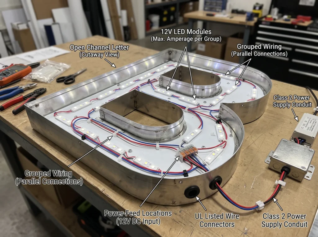
Illuminated channel letters use groups of LED modules distributed throughout letter housings. Each module usually has a specified DC operating voltage and rated electrical load. Where the system uses 12V constant-voltage modules, the power supply must deliver a regulated 12V output suitable for those modules—not simply the highest wattage available in a catalog.
A Class 2 configuration adds another selection requirement: the supplied circuit must meet the applicable Class 2 output limitations and product conditions. “12V” and “Class 2” are not synonyms. A 12V high-current supply with one unrestricted output is not automatically interchangeable with a supply designed and evaluated for separate Class 2 outputs. For the underlying definitions and limitations, see What Is a Class 2 Power Supply?.
12V Constant-Voltage Modules Inside Channel Letters
Sign manufacturers commonly arrange modules across letter strokes so the illuminated faces have reasonably even light distribution. The module manufacturer’s wiring diagram, maximum modules-per-run specification and mounting instructions govern the actual electrical connections. A letter with 20 modules and another with 45 modules do not necessarily need the same power-feed arrangement—even if the finished letters look similar.
How Class 2 Affects Distribution Between Letters
For a sign made from many separate letters, the engineering issue is often how to distribute a total load into permissible output circuits. A multi-channel Class 2 power supply is a practical candidate when the sign requires multiple appropriately limited output branches. It is not a license to combine channels or assume that the total nameplate rating belongs to one circuit.
UL Solutions has described how Class 2-powered multi-housing signs can benefit from the Class 2 wiring methods of the National Electrical Code, while also explaining changes to UL 48 sign-section labeling. These are system- and installation-dependent rules, not automatic exemptions for any 12V sign. See UL Solutions’ explanation of Class 2-powered multi-housing electric signs.
When One Output Is Not Enough
If the required load exceeds one output’s rating, an appropriate design may use several separate output channels or multiple supplies. Moving to a larger total wattage does not remove the need to calculate current, wiring and permissible loading on each branch. Physically spread-out letters may also be easier to feed from multiple nearby circuits than from one long, high-current cable run.
Gather These Project Details Before Calculating Wattage
Accurate sizing starts with a module datasheet and a sign layout, not a guess based on letter height.
| Required project data | Illustrative input | Why it changes the selection |
|---|---|---|
| LED module rated input | 12V DC | Must match the constant-voltage output |
| Maximum module power | 1.2W/module | Determines connected electrical load |
| Module quantity | 80 modules | Sets total watts and current |
| Letter and branch layout | Two groups of 40 | Determines output allocation |
| Maximum modules per permitted run | Per module datasheet | Constrains wiring topology |
| AC supply available at installation | 120Vac or 277Vac | Must be inside the driver’s rated input range |
| Distance from driver to LED feed | Measured on site | Affects cable resistance and voltage drop |
| Installation exposure | Dry, damp or wet | Affects enclosure and product suitability |
| Required approvals | Project-specific | Must be checked for the model and completed sign |
The numbers in this table are hypothetical design inputs, not specifications of a particular LED module.
Before purchasing, distinguish a manufacturer’s maximum electrical power from a nominal or typical number. If module power changes with product options or if the sign includes multiple module types, calculate the groups separately. For outdoor signs, confirm the actual location of the power supply: inside a suitable enclosure is not the same installation condition as exposed to rain.
How to Calculate the Right 12V Class 2 Power Supply Size
The calculation has four parts: connected watts, output current, design margin and per-output capacity.
Step 1 — Calculate Total LED Module Wattage
For one module type:
Total LED load (W) = Module quantity × Rated watts per module
If a sign contains 40 modules rated at 1.2W each:
40 × 1.2W = 48W
For several module types, add each group’s calculated wattage. If an accessory is powered from the same output, include its relevant input demand where permitted by the product configuration.
Step 2 — Convert the Load to 12V Output Current
For a 12V constant-voltage circuit:
DC load current (A) = DC load power (W) ÷ 12V
The 48W example draws a calculated 4A at 12V. This is the current the output and feeder must accommodate under the stated load assumptions. It does not establish the wire size by itself; the installation method, conductor length, temperature and applicable rules also matter.
Step 3 — Allow Sensible Operating Margin
As a planning example, a project may target 80% maximum utilization of a power supply’s nameplate rating:
Required nominal rating = Connected LED load ÷ 0.80
For 48W, this equals 60W. That is why a 12V/5A, 60W single-output model is a plausible starting point for the sample design. The 80% utilization figure is an engineering assumption for this worked example—not a universal Class 2 rule or a substitute for the manufacturer’s thermal derating curves. Higher ambient temperature, enclosed mounting and other operating conditions may require additional margin or another model.
Step 4 — Check Every Class 2 Output Separately
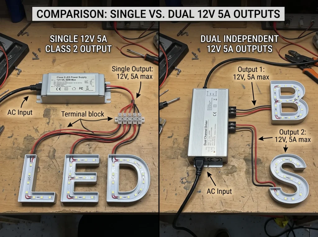
Consider two supplies that both have a 120W nameplate rating. One has two separate 12V/5A outputs; another might use a fundamentally different output configuration. Do not treat them as interchangeable simply because their combined wattage is the same.
For a verified two-output arrangement rated at 12V × 5A per output, the per-output nameplate maximum is 60W. With the illustrative 80% utilization target, an intended working load is up to 48W per output, assuming all other constraints are satisfied.
| Check | Two-output example |
|---|---|
| Combined rated output | 120W |
| Output 1 nameplate maximum | 12V × 5A = 60W |
| Output 2 nameplate maximum | 12V × 5A = 60W |
| Example design target on Output 1 | 48W / 4A |
| Example design target on Output 2 | 48W / 4A |
| Total example connected load | 96W |
The conclusion is operationally important: 96W connected in one 12V branch would demand 8A and exceed a 5A-rated output, even though the power supply’s combined rating says 120W.
For additional project-level considerations—AC input, dimming, enclosure and exact-model certification—see How to Choose a UL Class 2 LED Power Supply for North American Lighting Projects.
Single-Output vs Multi-Channel Class 2 Power Supplies for Channel Letters
When a 60W Single Output Makes Sense
A modest channel-letter installation may have one short, accessible LED distribution group. If the load is 48W at 12V, a 60W/5A output can satisfy the example’s 80% sizing assumption on paper. The designer must still verify cable losses, permitted module strings, ambient conditions and the exact model’s suitability.
A single output is often simpler when the sign has a compact load and the electrical routing is straightforward. It is less attractive when several distant letter groups would depend on one long feeder.
Why 120W Across Two Outputs Is Not One 120W Circuit
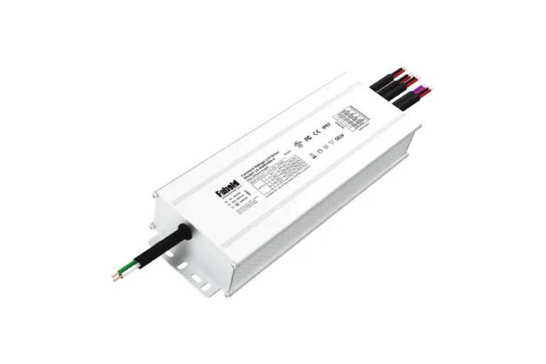
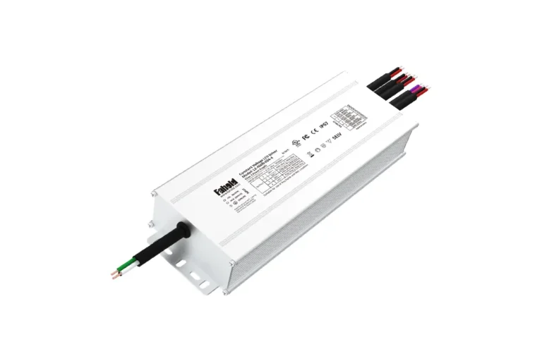
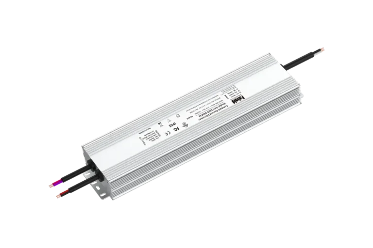
The FAHOLD L2-120X-012-2 model page specifies 120W total, 12V DC and 2 × 5A outputs. Its architecture allows two appropriately sized loads to be assigned to two separate outputs; it does not mean that one output can deliver the full 120W.
Allocate Letters by Actual Load, Not Equal Letter Count
A practical branch schedule might assign:
- Output A: letters A–C, 40 modules at 1.2W = 48W / 4A.
- Output B: letters D–F, 40 modules at 1.2W = 48W / 4A.
This is balanced electrically even if the physical dimensions of the letters differ. If one letter contains substantially more modules, divide the LED loads into allowed branch segments rather than assuming every letter belongs wholly to one output. Follow the LED module maker’s wiring instructions when doing so.
An unbalanced alternative—55 modules on Output A and 25 on Output B—would produce 66W / 5.5A on the first output and 30W / 2.5A on the second. The total still equals 96W, but Output A would exceed its 60W/5A nameplate rating. The correct fix is to redistribute load or choose a different approved architecture, not merely to point to the unused capacity on Output B.
Avoid These Wiring and Allocation Mistakes
- Treating the combined wattage as the allowable power from a single output.
- Connecting two regulated outputs in parallel or tying their positive outputs together without explicit manufacturer authorization.
- Assuming every separately marked output shares the same Class 2 conditions without checking the exact model documentation.
- Designing from average module power while ignoring rated maximum load.
- Ignoring voltage drop on long DC feeders or connector resistance.
- Choosing a cable solely on calculated current without checking installation and code requirements.
A multi-output supply can simplify segmentation, but it does not replace system design, protective measures or required evaluation.
Three Worked Sizing Examples for 12V Channel Letters
These are illustrative engineering scenarios, not field-tested projects. All assume 12V modules rated at 1.2W each, an illustrative 80% power-supply utilization target, suitably configured independent outputs, and a compliant installation to be verified separately.
Example 1 — Compact Channel Letters: 60W Single Output
A small shop sign contains 40 modules.
- Connected LED load: 40 × 1.2W = 48W.
- Calculated 12V current: 48W ÷ 12V = 4A.
- Minimum rating at 80% target: 48W ÷ 0.80 = 60W.
- Preliminary FAHOLD match: L2-060X-012, 12V/5A single output, 60W.
This arrangement has a small number of modules and one nominal output branch. If several letters are widely separated, the physical wiring design may still justify branch feeds or a different placement of the supply.
Decision: A 60W unit is a reasonable initial candidate when 48W represents the confirmed maximum connected load, installation derating permits the operating point, and the line-loss calculation is acceptable.
Example 2 — Medium Channel-Letter Sign: 120W Dual Outputs
A medium sign contains 80 modules distributed across multiple letters.
- Total load: 80 × 1.2W = 96W.
- Total calculated current: 96W ÷ 12V = 8A.
- Divide into two groups of 40: 48W / 4A per group.
- Candidate: L2-120X-012-2, 2 × 12V/5A, 120W total.
Each output carries 48W, satisfying the sample’s 80% utilization target per channel. If the 80 modules are instead distributed as 55 and 25 without further subdivision, the first output would be overloaded. The grouping must follow the connected watts, not the finished-letter count or the overall 120W label.
Decision: Use two independent load groups with documented connection points and a separate voltage-drop check for each feed.
Example 3 — Larger Multi-Letter Sign: 300W Five Outputs
A larger illuminated sign uses 200 modules.
- Total load: 200 × 1.2W = 240W.
- Total calculated 12V current: 240W ÷ 12V = 20A.
- Divide into five groups of 40: 48W / 4A per output.
- Candidate: L2-300X-012-5, 5 × 12V/5A, 300W total.
| Output branch | LED modules | Calculated load | Calculated current | Output nameplate |
|---|---|---|---|---|
| 1 | 40 | 48W | 4A | 12V / 5A / 60W |
| 2 | 40 | 48W | 4A | 12V / 5A / 60W |
| 3 | 40 | 48W | 4A | 12V / 5A / 60W |
| 4 | 40 | 48W | 4A | 12V / 5A / 60W |
| 5 | 40 | 48W | 4A | 12V / 5A / 60W |
| Total | 200 | 240W | 20A | 300W combined |
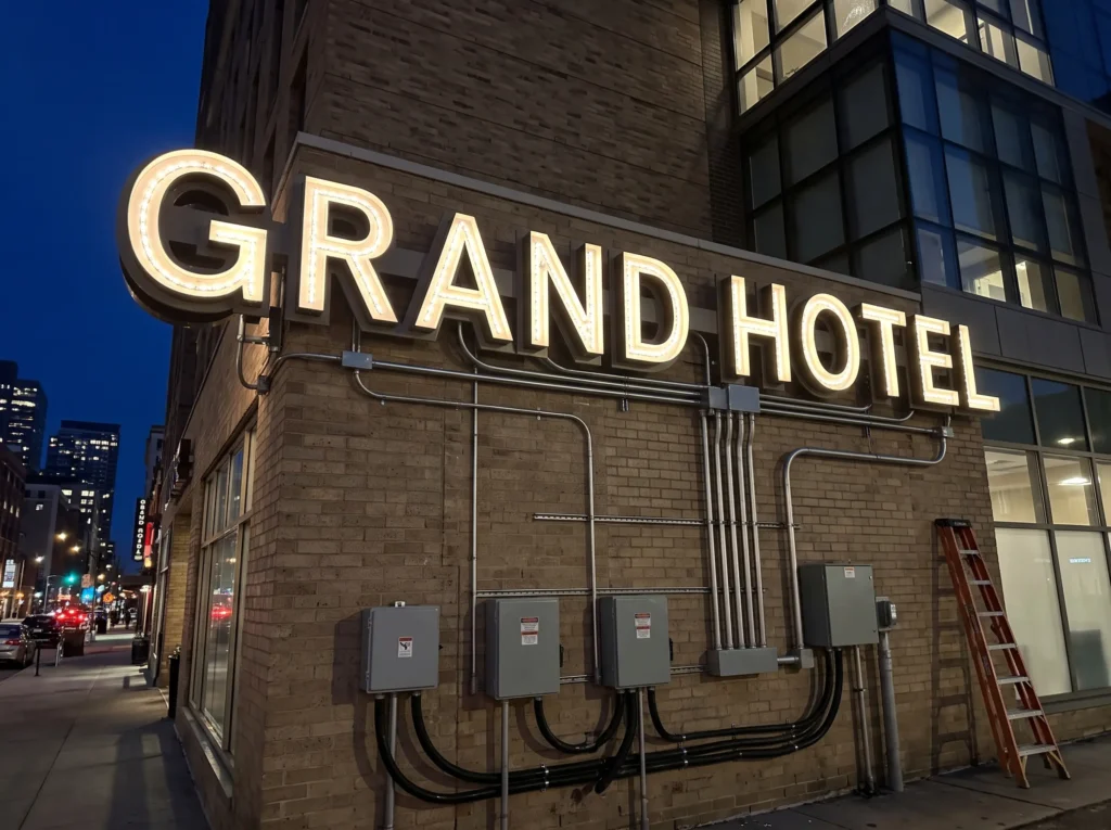
This design deliberately distributes the connected LED load across five independent outputs. It also makes the handoff to fabrication clearer: the shop can label letter groups and service points in the installation drawings. The final arrangement must comply with permissible LED module runs, conductor routing and the power supply’s installation instructions.
Decision: The 300W figure represents the entire unit, while each branch remains constrained by its 5A output. It is not an acceptable design to move unused capacity from one branch to another unless the manufacturer provides an approved method.
Compare the Three Scenarios
| Design | Total connected load | Branch allocation | Illustrative L2 candidate | Utilization |
|---|---|---|---|---|
| Small sign | 48W | 1 × 48W | L2-060X-012, 60W | 80% |
| Medium sign | 96W | 2 × 48W | L2-120X-012-2, 120W | 80% |
| Larger sign | 240W | 5 × 48W | L2-300X-012-5, 300W | 80% |
Do not use the table as an automatic approval list. It shows electrical sizing under stated assumptions. Check the exact model datasheet, certification scope, module wiring requirements, environmental protection and local installation requirements before procurement.
How to Reduce Voltage Drop in 12V Channel Letter Wiring
Voltage drop is especially relevant to 12V signs because a relatively small absolute voltage loss can represent a significant percentage of the supply voltage. Uneven current paths can also contribute to differences in brightness across letters, depending on how the LED modules regulate their current.
Why Long DC Feeders Matter
An approximate two-conductor feeder calculation is:
Voltage drop (V) ≈ Load current (A) × Round-trip conductor resistance (Ω)
For a uniform feeder, the round-trip resistance is approximately 2 × one-way distance × conductor resistance per unit length. Do not count only the positive wire; the return path contributes resistance too.
For example, assume a 4A branch, a 5m one-way copper run, and an illustrative conductor resistance of 0.0083Ω/m at about 20°C (approximately 14 AWG copper):
Voltage drop ≈ 4A × (2 × 5m × 0.0083Ω/m) = 0.332V, or approximately 2.8% of 12V.
At 15m one-way under the same simplified assumptions, the drop rises to approximately 1.0V (8.3%). This is why line length and feeder current must be considered alongside nameplate wattage.
These estimates exclude terminations, connectors, temperature effects, splices and the internal wiring of a distributed LED-module network. A 3% design target can be a useful project preference, but it is not a universal statutory voltage-drop limit for every Class 2 sign installation. Check the permitted module voltage range and the complete design. Read the fuller explanation in FAHOLD LED Power Supply Voltage Drop Guide.
Practical Ways to Improve a Long Sign Run
- Shorten the distance between the power supply and the start of each LED branch where feasible.
- Select an appropriate conductor size using both voltage-drop calculations and applicable wiring rules.
- Divide widely separated letter groups among outputs or use additional properly located supplies when appropriate.
- Review module manufacturer’s maximum modules-per-run instructions and approved feed arrangements.
- Validate the voltage at the load under realistic maximum operating conditions.
For a first-pass estimate of wattage, channel allocation and wire losses, use the FAHOLD Sign Lighting Power Supply Sizing Calculator. Its results are engineering estimates, not an automatic substitute for model review or compliance checks.
Which FAHOLD 12V Class 2 LED Power Supply Should You Choose?
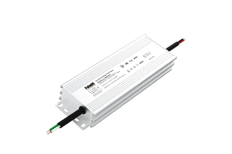
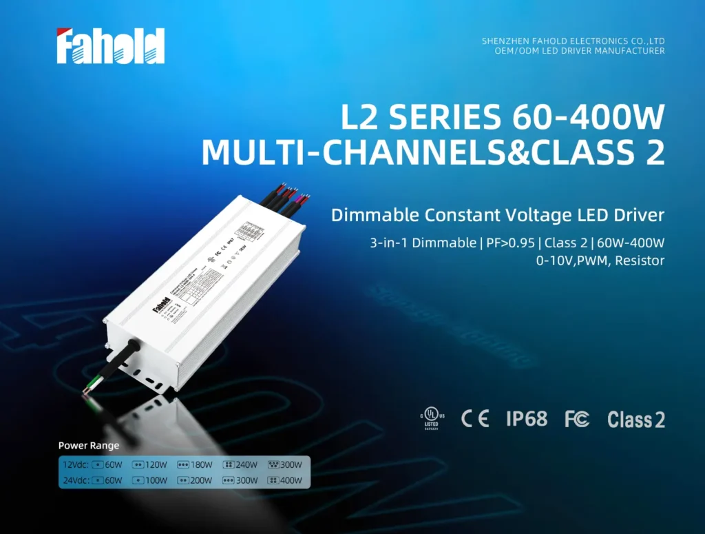
FAHOLD’s L2 family includes 12V constant-voltage models with one to five output channels. Its publicly listed model table gives the following nominal configurations:
| FAHOLD L2 model family | Rated DC output structure | Combined rated output | Typical selection situation |
|---|---|---|---|
| L2-060X-012 | 1 × 12V / 5A | 60W | One compact LED load group |
| L2-120X-012-2 | 2 × 12V / 5A | 120W | Two independently fed groups |
| L2-180X-012-3 | 3 × 12V / 5A | 180W | Three-group sign distribution |
| L2-240X-012-4 | 4 × 12V / 5A | 240W | Four distribution groups |
| L2-300X-012-5 | 5 × 12V / 5A | 300W | Larger signs with five branches |
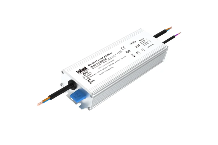
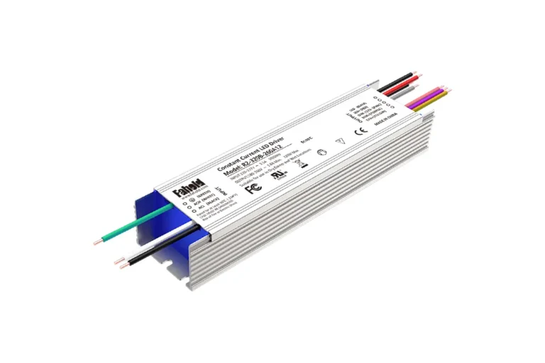
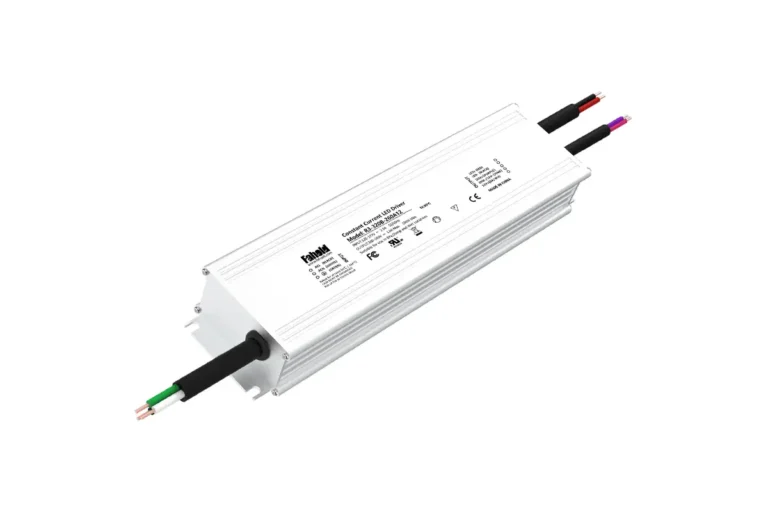
The series specifies 100–277Vac input for these listed models. The model notation X denotes a model-family variable; request the complete purchasable model number and documentation rather than treating the letter X as a final orderable variant. Output, dimming and enclosure details should be checked for that exact configuration.
For a full product table and additional 24V options, see FAHOLD L2 Multi-Channel Class 2 LED Power Supply Series. Buyers comparing multiple sign-power-supply formats can also review the Class 2 Multi-Channel product category.
What About Slim, Single-Output Sign Power Supplies?
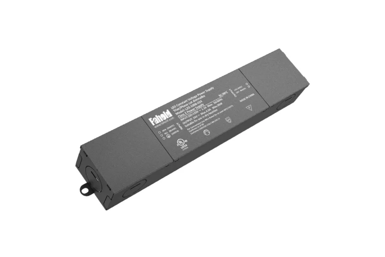
Some narrow channel-letter cabinets may favor the physical dimensions of the L2-E compact sign-power platform. However, a slim 12V sign supply must not be assumed to have the required Class 2 listing or output classification simply because it is used with LED modules. Confirm the exact model and evidence before specifying it for a Class 2-required project.
Before You Approve a Model
Verify the exact input rating, output-channel count and current, thermal derating, housing conditions, environmental ratings, permissible wiring arrangement, LED-module compatibility, and certification documentation. If the drawing specifies a 12V/5A branch but an installed product has a different output topology, the electrical design needs another review.
North American Compliance and Installation Checklist
For illuminated electric signs, the power supply, the LED modules and the completed sign assembly are different compliance subjects. UL Solutions identifies UL 48 for electric signs, UL 879 for electric sign components and NEC Article 600 among common sign-related requirements. The applicable requirements depend on the project’s design, certification program and jurisdiction.
Before approving a power supply for a North American channel-letter project, ask:
- Exact model: Does the actual ordering code—not just the family brochure—have the needed Class 2 output configuration and relevant certification evidence?
- Sign-system scope: Does the sign maker’s assembly and installation approach meet the applicable electric-sign rules and listing conditions?
- Component compatibility: Do the LED modules allow the proposed 12V feeds, current and grouping?
- Field wiring: Are conductor types, protection, separation, terminations and routing appropriate for the installation?
- Environment: Is the power supply suitable for the actual dry, damp or wet location and its mounting temperature?
- Input: Is the installed AC supply covered by the exact driver’s input-voltage rating?
For product-level evidence, use the manufacturer’s current documents and, when relevant, UL Product iQ to look up the company, file and model. A claim on a sales page is not by itself confirmation that every variant has identical certification coverage.
Engineering information here is for preliminary specification. Final sign design, electrical installation and approval must follow the equipment instructions, applicable codes and the authority having jurisdiction.
Final Channel Letter Power Supply Design Checklist
Need Help With Your LED Power Supply Project?
Tell us what you are working on. We will review your application and recommend the most relevant FAHOLD solution.
The best first purchasing question is not simply “Do you have a 120W Class 2 power supply?” It is: “Here are our module loads and letter groups—can you confirm the appropriate 12V output architecture and exact certified model?” That produces a more useful answer for production planning.
Frequently Asked Questions
How many 12V LED modules can a 60W Class 2 power supply run?
It depends on the module’s maximum rated wattage, the supply’s permitted operating conditions and wiring limits. With 1.2W modules and the example 80% utilization target, a 60W/5A output supports a planning load of 48W, or 40 modules. The module manufacturer’s maximum modules-per-run specification still applies.
Can I use a 120W Class 2 LED power supply for channel letters?
Yes, if the selected model’s configuration fits the design. For example, FAHOLD’s L2-120X-012-2 provides two rated 12V/5A outputs. A 96W load can be divided as 48W on each output. Do not attempt to draw the full 120W through one 5A output.
How should I divide channel letters across two or more outputs?
Calculate watts for each letter or letter segment, then assign modules so that each separate output stays within its permissible current, wattage, utilization and wiring limits. Grouping letters only by their physical number can produce electrical imbalance. Check cable distance for each branch as well.
Does every channel letter need its own power supply?
No. Several letters may be served by approved distribution arrangements and suitably rated outputs. The correct architecture depends on electrical load, cable routing, module instructions, Class 2 conditions and the sign’s installation requirements. A multi-output supply is one option, not the only permissible topology.
How much power supply headroom should I allow?
There is no single headroom percentage that makes every installation compliant. An 80% utilization target is a conservative planning assumption used in this guide. Follow the actual driver manufacturer’s derating and loading instructions, and account for maximum ambient temperature, enclosure, duty cycle and module tolerances.
Can I install a 12V Class 2 power supply in an outdoor sign?
Only where the specific power supply and installation method are suitable for the exposure. Outdoor signs may use protected enclosures, damp- or wet-location-rated products and other necessary measures. Verify the exact model’s environmental rating and the full sign installation; a Class 2 output marking alone does not establish outdoor suitability.
Need a 12V Class 2 Power Supply for Your Channel Letter Project?
If you manufacture illuminated letters or source power supplies for a sign program, FAHOLD can help evaluate a suitable L2 output configuration using the actual LED-module data, letter-group layout and installation conditions.
To request a model recommendation, send:
- LED module datasheet or module rated voltage and watts per unit.
- Quantity of modules in each letter or planned branch.
- AC input voltage and installation environment.
- Approximate feeder lengths, conductor details and any control requirements.
- Target model, required certification documents and estimated order quantity.
Explore the FAHOLD L2 12V multi-channel power supply range or send your channel-letter requirements to the FAHOLD engineering and sales team for model matching, sample discussions and a project quotation.