Table of Contents
Connecting an LED strip to a power supply requires more than joining two wires. The power supply must first match the LED strip voltage, total wattage, output-current requirement, and control architecture.
For most conventional low-voltage LED strips, the basic connection is:
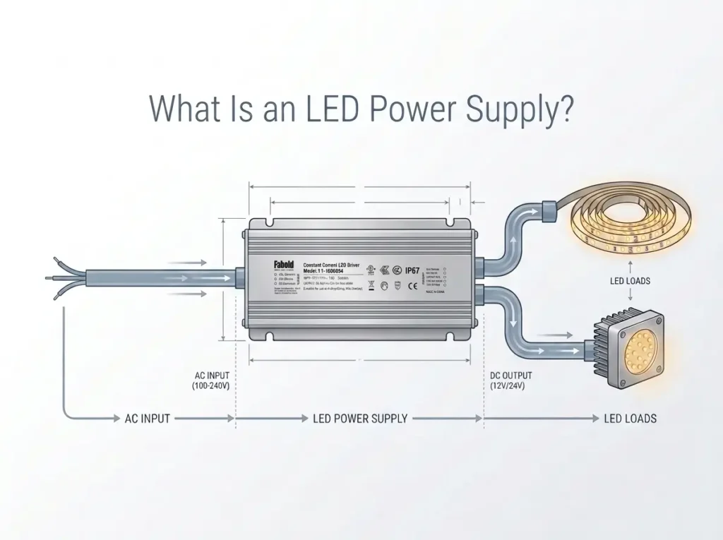
AC Input → Constant Voltage LED Driver → LED Strip
If a controller is used:
AC Input → LED Driver / Power Supply → Controller → LED Strip
Before connecting anything, verify that the strip and driver are electrically compatible.
Safety: The low-voltage DC side of an LED-strip system is different from the AC mains input side. Installation or testing involving exposed mains-voltage conductors should be performed by a qualified person in accordance with applicable electrical regulations. OSHA identifies electrical work as a shock, electrocution, fire, and explosion hazard and restricts work on exposed energized equipment to appropriately qualified personnel. See OSHA electrical safety guidance.
Quick Answer: How Do You Connect LED Strip Lights to a Power Supply?
For a typical 12V or 24V constant-voltage LED strip:
- Confirm the LED strip rated voltage.
- Select a constant-voltage power supply with the same output voltage.
- Calculate the total LED-strip load.
- Verify the driver has sufficient output-current and power capacity.
- Switch off and isolate power before installation.
- Connect the driver positive DC output to the strip positive input.
- Connect the driver negative DC output to the strip negative input.
- If using a controller, install it between the driver and LED strip according to the controller wiring diagram.
- Check polarity and terminal security before energizing the system.
- Test the installation and check for abnormal heating, flicker, or voltage drop.
Understand the LED Strip Power Architecture First
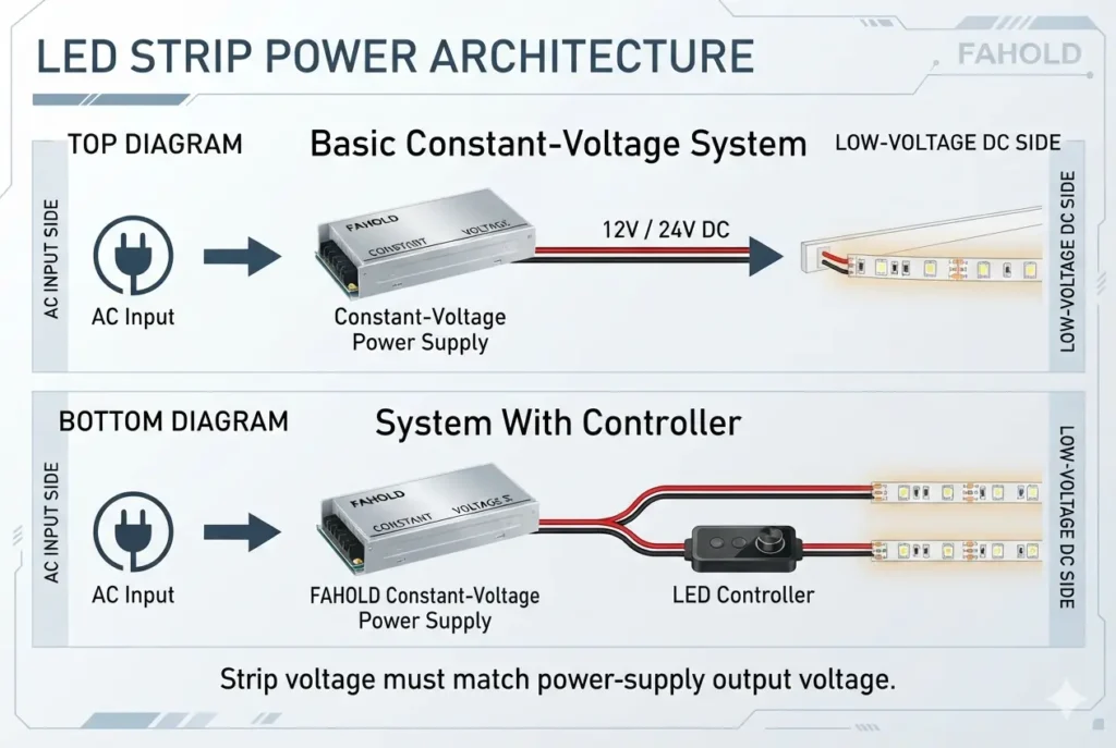
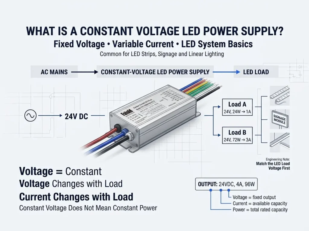
Most common 12V and 24V LED strips operate as constant-voltage loads.
If you are unsure why constant-voltage and constant-current systems use different driver architectures, review what an LED power supply is and how it differs from an LED driver.
A general overview of common strip architectures is available in the LED strip light reference.
Typical system:
AC Mains
   ↓
Constant Voltage LED Driver
   ↓
12V / 24V DC
   ↓
LED Strip
The LED driver converts the available input power into the DC output required by the strip.
The output voltage must match the strip.
| LED Strip | Driver Output |
|---|---|
| 12V strip | 12V DC |
| 24V strip | 24V DC |
| 48V strip | 48V DC, if specified |
Do not connect a 12V strip to a 24V constant-voltage output.
Step 1: Check the LED Strip Voltage
Look for the nominal voltage on:
- the strip PCB;
- datasheet;
- packaging;
- label;
- product specification.
Connecting a 12V LED Strip
Use a 12V constant-voltage driver.
Typical architecture:
AC Input
   ↓
12V Constant Voltage Driver
   ↓
12V LED Strip
Connecting a 24V LED Strip
Use a 24V constant-voltage driver.
AC Input
   ↓
24V Constant Voltage Driver
   ↓
24V LED Strip
The driver wattage may be higher than the actual LED load, but its output voltage must remain correct for the strip.
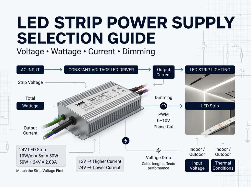
Step 2: Calculate the LED Strip Load Before Wiring
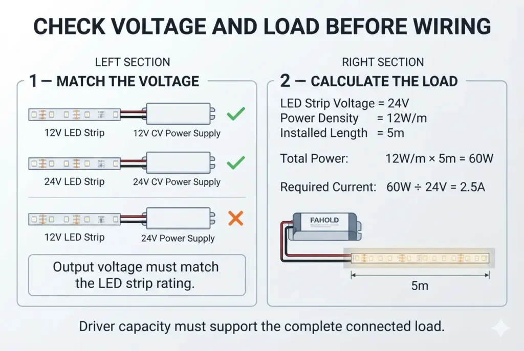
Before connecting the strip, calculate the total load.
Use:
Total Power = LED Strip W/m × Total Length
Example:
- LED strip: 24V;
- consumption: 12W/m;
- installed length: 5m.
Calculation:
12W/m × 5m = 60W
Output-current requirement:
60W ÷ 24V = 2.5A
The driver must support the required load under the intended thermal and operating conditions.
Before wiring the system, confirm the driver is correctly sized using the LED strip power supply selection guide.
Step 3: Identify the DC Output Polarity
Most constant-voltage LED strips have positive and negative DC terminals.
Typical markings include:
+-V+V-+12V+24VGND
The exact marking depends on the product.
For a simple single-color strip:
Driver V+  →  LED Strip +
Driver V-  →  LED Strip -
Correct polarity matters.
Reversing polarity may prevent the strip from operating and, depending on the circuit design, can create additional electrical stress.
Always follow the LED strip and driver documentation.
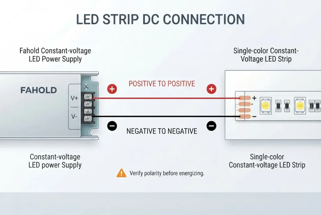
Step 4: Make the Low-Voltage Connection
With the system de-energized:
- Verify driver output voltage.
- Identify the driver DC output terminals or leads.
- Identify the strip positive and negative terminals.
- Connect positive to positive.
- Connect negative to negative.
- Secure the connection using the installation method specified for the system.
- Check for exposed conductors, loose terminals, or reversed polarity.
Possible connection methods include:
- approved terminal blocks;
- manufacturer-specified connectors;
- soldered joints;
- wiring harnesses;
- suitable plug connectors.
The connection method should be rated for the required voltage, current, temperature, and installation environment.
Step 5: Connect the AC Input Safely
The driver AC input side may operate at hazardous mains voltage.
Typical drivers may identify conductors or terminals for functions such as:
- line/live;
- neutral;
- protective earth, where required.
However, conductor colors, grounding requirements, disconnecting means, enclosure requirements, and wiring methods vary by market and installation.
Do not rely on a generic internet wiring diagram as a substitute for:
- the driver installation instructions;
- local electrical codes;
- the final luminaire wiring design;
- qualified electrical installation.
Where exposed energized parts are involved, OSHA 1910.333 provides safety requirements concerning work practices around energized electrical equipment.
For OEM and professional projects, mains-side installation should be part of the complete product-safety design.
How to Connect a 12V LED Strip to a Power Supply
A standard single-color 12V system is conceptually simple:
AC Mains
   ↓
12V Constant Voltage Driver
   ↓
   +12V ─────────→ LED Strip +
   0V/GND ───────→ LED Strip -
Before energizing:
- confirm the strip is rated 12V;
- confirm the driver output is 12V;
- confirm total strip wattage;
- confirm output-current capacity;
- confirm polarity;
- confirm secure connections.
Do not connect the LED strip directly to mains voltage unless the strip is specifically designed and certified as a mains-voltage product.
How to Connect a 24V LED Strip to a Power Supply
The same principle applies:
AC Mains
   ↓
24V Constant Voltage Driver
   ↓
   +24V ─────────→ LED Strip +
   0V/GND ───────→ LED Strip -
For longer runs, 24V systems can reduce current relative to a 12V system of the same wattage, but voltage drop and conductor sizing still need to be checked.
How to Connect an LED Controller to a Power Supply
When a separate controller is required, it is normally placed on the low-voltage side of a compatible constant-voltage system.
Typical architecture:
AC Mains
   ↓
Constant Voltage Power Supply
   ↓
LED Controller
   ↓
LED Strip
The controller must be compatible with:
- driver output voltage;
- LED strip voltage;
- total current;
- strip type;
- control method.
For example, a controller rated only for 12V should not automatically be used in a 24V system.
Likewise, the controller’s maximum current per channel and total power capacity must not be exceeded.
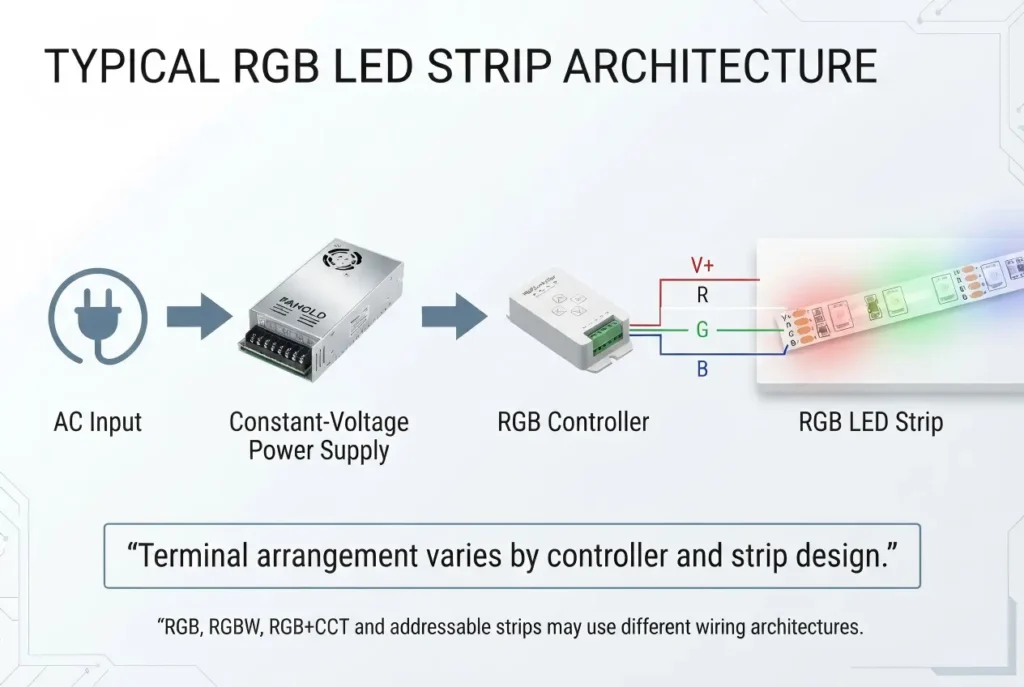
How to Connect RGB LED Strip Lights to a Power Supply
RGB strips have more conductors than a single-color strip because the controller independently regulates the red, green, and blue channels.
A common architecture is:
AC Input
   ↓
Constant Voltage Driver
   ↓
RGB Controller
   ↓
RGB LED Strip
The controller output may include terminals such as:
V+
R
G
B
The exact wiring arrangement depends on whether the strip is:
- common-anode;
- common-cathode;
- RGB;
- RGBW;
- RGB+CCT;
- digitally addressable.
Do not assume all RGB strips use the same connection method.
RGB Connection Checklist
Confirm:
- Strip voltage.
- Controller input voltage.
- Controller output architecture.
- Channel arrangement.
- Current per channel.
- Total driver power.
- Correct terminal mapping.
For addressable LED strips, the data/control architecture is different from a conventional analog RGB strip and must follow the controller manufacturer’s wiring requirements.
How to Connect Multiple LED Strips to One Power Supply
Multiple constant-voltage LED strips can often share one driver if:
- all strips use the same rated voltage;
- total connected power is within driver capacity;
- wiring and branch current are correctly designed.
A typical branch architecture is:
                ┌── LED Strip A
Driver Output ──┼── LED Strip B
                └── LED Strip C
This is a parallel distribution concept.
Example
Three 24V strips consume:
- Strip A: 30W;
- Strip B: 20W;
- Strip C: 25W.
Total:
30W + 20W + 25W = 75W
Required current:
75W ÷ 24V = 3.125A
The driver must support the combined load.
The designer must also check:
- branch current;
- conductor size;
- connector ratings;
- voltage drop;
- fuse/protection strategy where applicable;
- driver output-terminal capacity.
Should Multiple LED Strips Be Connected in Series or Parallel?
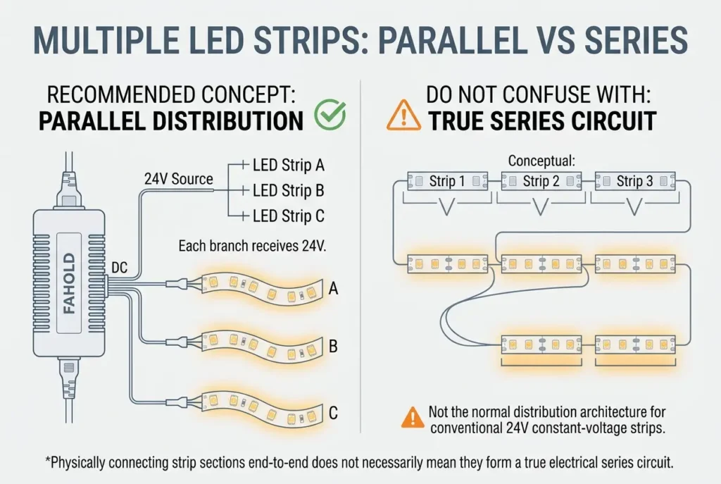
Conventional constant-voltage strips are generally distributed from a common constant-voltage source using parallel branches rather than being connected as one long electrical series circuit.
For example:
          ┌── Strip A
24V DC ───┼── Strip B
          └── Strip C
Each branch receives the intended system voltage.
However, the exact layout still depends on:
- strip design;
- maximum run length;
- cable routing;
- power injection;
- driver location.
Do not confuse “physically connecting strips end-to-end” with a true electrical series circuit.
How Many LED Strips Can One Power Supply Run?
There is no fixed number.
The limit depends on:
Total Strip Power ≤ Permitted Driver Load
and:
Total Current ≤ Permitted Driver Output Current
For example, if each 24V strip branch consumes 24W:
- 1 strip = 24W;
- 2 strips = 48W;
- 3 strips = 72W;
- 4 strips = 96W.
A suitable driver must cover the total load and operate within its specified loading and thermal conditions.
Physical distribution can become a limiting factor even before total wattage reaches the driver maximum.
Voltage Drop in LED Strip Wiring
Long low-voltage cable runs can cause voltage drop.
Voltage drop increases with factors such as current and conductor resistance.
Symptoms can include:
- dimmer LEDs at the end of the run;
- brightness variation;
- color shift;
- unstable operation.
Possible engineering solutions include:
- larger conductor cross-section;
- shorter cable runs;
- multiple power-injection points;
- locating the driver closer to the load;
- splitting the load across multiple drivers;
- using a higher system voltage where the strip design allows it.
Do not increase driver output voltage beyond the LED strip rating simply to compensate for poor wiring design.
How to Connect Long LED Strip Runs
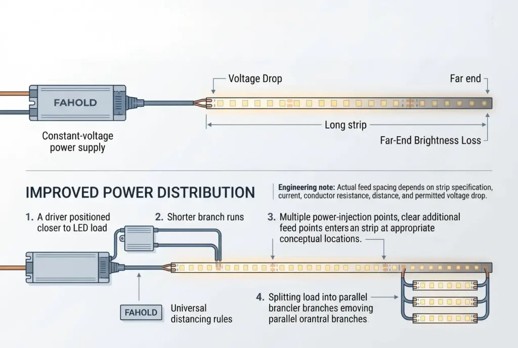
Long installations should be designed as a power-distribution problem rather than a single-strip problem.
Instead of:
Driver → Very Long Strip → Very Long Strip → Very Long Strip
a project may use:
              ┌→ Strip Section A
Driver ───────┼→ Strip Section B
              └→ Strip Section C
or multiple drivers located closer to individual loads.
The appropriate architecture depends on:
- total power;
- run length;
- voltage drop;
- conductor size;
- maintenance access;
- physical installation.
Connecting LED Strips With 0-10V Dimming
A 0-10V dimmable driver includes a separate control interface in addition to the LED power output.
Conceptually:
AC Input
   ↓
0-10V Dimmable Driver
   ├── LED Output → LED Load
   └── 0-10V Control → Lighting Controller
The 0-10V control conductors are not the same as the LED output conductors.
For compatible outdoor projects, review FAHOLD’s 0-10V LED drivers.
Always follow the specific driver wiring diagram because sourcing/sinking behavior, dim-to-off operation, auxiliary power, and control wiring can vary by product.
Connecting LED Strips With DALI-2 Control
DALI uses a digital control bus rather than a simple analog dimming voltage.
A simplified architecture is:
AC Input
      ↓
DALI-Compatible LED Driver
      ├── LED Output → LED Load
      └── DALI Bus ↔ DALI Control System
DALI control gear and communication requirements are defined within the DALI Alliance / IEC 62386 framework.
For suitable outdoor applications, review FAHOLD’s DALI-2 LED drivers.
The DALI bus should not be confused with the LED driver DC output.
Connecting a Dimmable LED Strip System
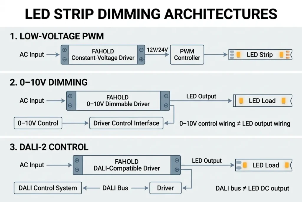
A dimmable installation may take different forms.
Low-Voltage PWM Controller
AC
↓
CV Driver
↓
PWM Controller
↓
LED Strip
0-10V Driver
AC
↓
0-10V Driver
↓
LED Strip / Compatible Load
↑
0-10V Control
DALI Driver
AC
↓
DALI Driver
↓
LED Load
↑
DALI Bus
Phase-Cut Driver
AC
↓
Compatible Phase-Cut Dimmer
↓
Compatible Dimmable Driver
↓
LED Load
The term dimmable LED drivers covers multiple incompatible control architectures, so the protocol must be defined before wiring.
Indoor and Outdoor Connection Requirements
Outdoor wiring needs additional environmental consideration.
Relevant factors include:
- water exposure;
- dust;
- cable glands;
- connector protection;
- enclosure sealing;
- temperature;
- condensation;
- mounting orientation.
The enclosure protection classification system is defined under IEC 60529.
An IP rating applies to the tested enclosure configuration. It does not mean every connector, cable joint, and field termination in the completed installation automatically has the same protection.
For outdoor projects, the complete installation—not only the driver housing—must be considered.
Common LED Strip Connection Mistakes
1. Connecting the Wrong Voltage
A 12V strip and 24V driver are not compatible simply because both are constant-voltage products.
2. Reversing DC Polarity
Positive and negative terminals must be identified correctly.
3. Undersizing the Power Supply
The driver must support the complete connected load.
4. Ignoring Controller Current Limits
An RGB or PWM controller may become the limiting component even when the power supply has enough wattage.
5. Using Long Thin Wires
This can increase voltage drop and reduce LED performance.
6. Connecting Too Many Loads to One Terminal
Terminal ratings and conductor capacity must be respected.
7. Treating the AC and DC Sides as Equivalent
The mains input presents a fundamentally different safety risk from the low-voltage LED output.
8. Assuming All Dimming Wires Are the Same
0-10V, DALI, PWM, and phase-cut systems use different control methods.
9. Ignoring Environmental Protection
An outdoor-rated driver does not automatically make exposed field connections suitable for outdoor use.
10. Working on Energized Mains Wiring
Where mains circuits are involved, de-energize the system and use qualified electrical personnel. OSHA’s rules on energized electrical work emphasize qualification and appropriate safety practices; see OSHA 1910.333.
LED Strip Power Connection Checklist
Before energizing the installation, verify:
| Item | Check |
|---|---|
| Strip voltage | Matches driver output |
| Driver type | Constant voltage where required |
| Total wattage | Within driver operating range |
| Output current | Sufficient for complete load |
| DC polarity | Correct |
| Controller voltage | Matches system |
| Controller current | Within rating |
| Terminations | Secure |
| Cable size | Suitable for current and distance |
| Voltage drop | Evaluated |
| Dimming protocol | Compatible |
| Environment | Suitable for installation |
| IP protection | Appropriate where required |
| Thermal conditions | Within driver specification |
| AC wiring | Installed according to applicable rules |
Troubleshooting: LED Strip Does Not Turn On
If the strip does not operate, use a structured diagnostic process.
1. Verify the Strip Voltage
Confirm the driver output specification matches the strip.
2. Check Power Availability
Confirm the driver is receiving the intended input supply using appropriate safe testing procedures.
3. Check DC Output
A qualified person can verify whether the driver DC output is present and within the expected range.
4. Check Polarity
Confirm positive and negative connections.
5. Check the Controller
If a controller is installed, determine whether it is receiving power and providing the expected output.
6. Isolate Branches
In a multi-strip system, determine whether the fault affects:
- one branch;
- the controller;
- the entire driver output.
7. Check for Overload or Protection Operation
An overloaded or faulted system may cause some drivers to enter a protection mode.
Do not bypass protective functions to force the system to operate.
Troubleshooting: LED Strip Is Dim at the Far End
Likely areas to investigate include:
- voltage drop;
- excessive strip length;
- undersized conductors;
- insufficient power injection;
- poor connections;
- excessive branch current.
Measure the system according to safe electrical practices and compare the voltage at the driver output with the voltage available at the load.
Troubleshooting: LED Strip Flickers
Possible causes include:
- incompatible dimming architecture;
- unstable power supply;
- incorrect controller;
- overloaded driver;
- loose connections;
- thermal protection;
- incompatible minimum load or dimming behavior.
Flicker should not automatically be blamed on the LED strip.
Diagnose the system from:
Input Power → Driver → Controller → Wiring → LED Load
What Information Should a Buyer Provide for an LED Strip Driver Project?
For an OEM, project contractor, distributor, or lighting manufacturer, provide:
- application;
- input voltage;
- LED strip voltage;
- watts per meter;
- total strip length;
- total system wattage;
- required output current;
- dimming/control method;
- controller type;
- installation environment;
- target market;
- certification requirement;
- quantity;
- project schedule.
This information allows the driver manufacturer to evaluate compatibility before recommending a product.
Selecting a FAHOLD Driver for LED Strip Wiring
For professional LED strip and linear-lighting systems, define the complete load and control architecture before choosing a driver.
Projects using analog control can review FAHOLD’s 0-10V LED drivers.
Projects using DALI digital control can review FAHOLD’s DALI-2 LED drivers.
For other systems, constant voltage LED drivers, dimmable LED drivers, and LED strip lighting applications should be matched to the verified project requirements before a model is selected.
Need Help Matching a Driver to Your LED Strip System?
For a commercial LED strip, signage, architectural, OEM, or linear-lighting project, prepare:
- input voltage;
- LED strip voltage;
- total wattage;
- required output current;
- dimming protocol;
- installation environment;
- target market;
- estimated quantity.
Request a Quote to discuss the appropriate LED driver specification for your project.
Frequently Asked Questions
How do you connect LED strip lights to a power supply?
For a typical constant-voltage strip, match the driver output voltage to the strip, calculate the complete load, switch off the supply, and connect the driver positive DC output to the strip positive terminal and negative output to the strip negative terminal. Mains-side installation should follow the driver instructions and applicable electrical rules.
How do I connect a 12V LED strip to a power supply?
Use a 12V constant-voltage power supply with sufficient output capacity. Connect its 12V positive output to the strip positive terminal and its negative output to the strip negative terminal while the system is de-energized.
How do I connect a 24V LED strip to a power supply?
Use a 24V constant-voltage driver and match the DC polarity correctly. Verify the total strip wattage and output-current requirement before energizing the system.
Can multiple LED strips connect to one power supply?
Yes, when the strips use the same rated voltage and their combined load remains within the driver operating limits. Branch wiring, terminal capacity, conductor size, and voltage drop must also be considered.
How do I connect an RGB LED strip to a power supply?
A conventional analog RGB strip normally connects through a compatible RGB controller. The common architecture is power supply → RGB controller → RGB strip. Verify voltage, common-terminal configuration, channel mapping, and controller current capacity.
How do I connect an LED controller to a power supply?
Match the controller input voltage to the power supply output, verify current capacity, and connect it according to the controller manufacturer’s terminal diagram. The controller is typically installed between a constant-voltage power supply and the LED strip.
Can I connect an LED strip directly to AC mains?
Not if it is a conventional 12V, 24V, or other low-voltage DC strip. It requires an appropriate driver or power supply. Only products specifically designed and certified for mains-voltage operation should be connected according to their dedicated installation instructions.
Why does my LED strip get dimmer toward the end?
Voltage drop is a common cause. Cable resistance, strip length, current, connection quality, and conductor size can reduce the voltage available farther from the power source.
Should multiple LED strips be connected in series or parallel?
Conventional constant-voltage LED-strip branches are typically supplied in parallel so each branch receives the intended system voltage. The exact installation should follow the strip and driver specifications.
Can a dimmable driver connect directly to an LED strip?
It depends on the driver output architecture and dimming method. The driver must match the LED strip voltage/load and the controller protocol. 0-10V, DALI, PWM, and phase-cut systems have different wiring architectures.
Need Help With Your LED Power Supply Project?
Tell us what you are working on. We will review your application and recommend the most relevant FAHOLD solution.