Table of Contents
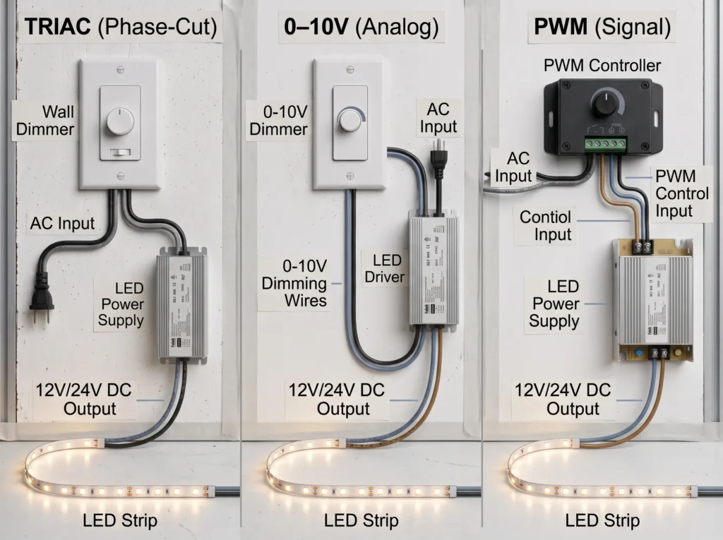
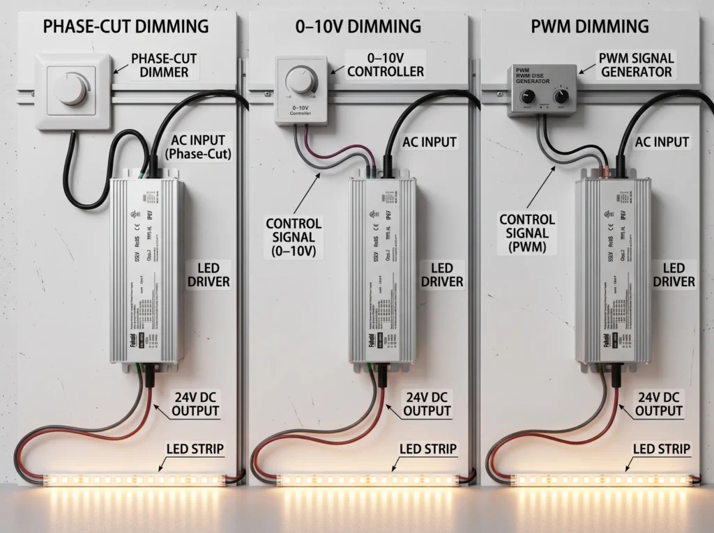
TRIAC, 0–10V and PWM are different ways of commanding LED brightness—not interchangeable connections on every dimmable power supply. TRIAC or other phase-cut controls modify the AC waveform seen by a compatible driver; 0–10V typically uses a separate low-voltage analog control circuit; and PWM uses a pulsed signal whose duty cycle represents the requested dimming level. To select a Class 2 dimmable LED power supply for a 12V or 24V lighting project, verify the existing controller, the driver’s supported input interface, the LED load and each Class 2 output circuit before ordering.
For commercial project, this decision is usually simpler when approached in the following order: identify the controller → match the dimming interface → confirm AC input → match 12V/24V output and load → check enclosure and certification → test the actual dimming combination.
| Project requirement | Start by evaluating | Critical compatibility question |
|---|---|---|
| Existing 120Vac wall dimmer | Phase-cut / TRIAC-compatible driver | Is the dimmer forward-phase, reverse-phase, or adaptable—and is the selected driver approved for it? |
| Building lighting control with separate dimming pair | 0–10V driver | Does the controller source or sink current, and how is complete OFF achieved? |
| Controller with specified pulse output | PWM-input-compatible driver | Does its accepted PWM frequency, voltage level and polarity match the controller? |
| Several controller types across an OEM product family | Suitable multi-mode / 5-in-1 platform | Which interfaces are supported by the exact configuration, not merely the series brochure? |
What Makes a Class 2 LED Power Supply Dimmable?
A Class 2 output designation concerns the limited-energy characteristics of the power source. Dimmable describes the driver’s ability to respond to a specified control method. The two specifications solve different problems. A 24V power supply may be Class 2 but non-dimmable; another may be dimmable yet have an output configuration that does not satisfy a project’s Class 2 requirement.
For a longer explanation of the safety classification, refer to FAHOLD What Is a Class 2 Power Supply? The discussion here is about control compatibility and system selection.
Class 2 output limits and dimming control are separate checks
Class 2 compliance must be verified for the exact model and output circuit. When a driver has multiple outputs, the combined enclosure wattage cannot automatically be assigned to one Class 2 branch. Dimming does not change the need to check each circuit’s rating or to follow the approved wiring arrangement.
In the United States, LED drivers with integral wired control interfaces can also raise control-circuit construction and evaluation questions. UL Solutions’ discussion of UL 8750 wired controls explains why output classification and externally connected control circuits may need separate attention.
Constant-voltage power supplies and control interfaces
This guide focuses on 12V/24V constant-voltage drivers used with compatible LED strips, linear fixtures, cabinet lighting, display lighting and architectural details. The driver regulates DC output voltage while its dimming interface receives a brightness command. The physical method used to vary LED light output can differ internally by design.
A constant-current driver for a streetlight or integrated LED array is not a drop-in alternative simply because it also advertises 0–10V or PWM control. Output topology must match the LED load first.
Compatibility involves the controller, driver and LED load
Consider a lighting system as three linked specifications:
- Controller: make, exact model, output signal, load rating and switching behavior.
- Power supply: allowable AC input, required dimming interface, 12V/24V DC output, load range and dimming characteristics.
- LED load: rated input voltage, connected watts, wiring distribution and response at low light levels.
Compatibility cannot be established from the word dimmable on two unrelated product labels. Actual performance—smoothness, minimum light level, flicker and reliable switching—should be confirmed with a representative system sample.
TRIAC vs 0–10V vs PWM Dimming: Key Differences
| Parameter | TRIAC / phase-cut | 0–10V analog | PWM command input |
|---|---|---|---|
| Information carried by | Altered AC mains waveform | Low-voltage analog control level | Pulse duty cycle |
| Typical control connection | Compatible line-voltage dimmer before driver | Separate low-voltage control conductors | Manufacturer-defined PWM control terminals |
| Common use | 120V wall-dimmer retrofit, hospitality, cabinetry | Commercial and architectural lighting zones | Specialized LED controls and OEM integration |
| Main matching variables | Forward/reverse phase, dimmer model, minimum load | Source/sink, control current, curve, OFF behavior | Logic amplitude, frequency, polarity, common reference |
| Frequent symptom | Flicker or buzzing at low levels | Minimum brightness or failure to switch OFF | No response, unstable response or temporal light artifacts |
| FAHOLD platform to investigate | L2D Type B | L2-A compatible configuration | L2-A or L2-F compatible configuration |
This table compares the signal delivered to the power supply. It does not mean that a 0–10V driver cannot use PWM internally, or that a driver which accepts a PWM input must switch its 24V output with the same waveform. These distinctions matter when comparing installation drawings and datasheets.
The important distinction: control input versus LED output
A PWM command may be a relatively low-power signal entering the driver’s control circuitry. By contrast, a PWM LED-strip output controller deliberately switches power supplied to the load. One cannot assume that a controller’s high-current strip output is safe to connect to a driver’s PWM input, or that an input marked PWM can drive LED strips directly. Verify terminal purpose, electrical limits and the required reference/return arrangement.
How Does TRIAC Dimming Work With a Class 2 LED Power Supply?
Phase-cut dimming changes which parts of each AC half-cycle reach the connected driver. A compatible power supply interprets that altered waveform and adjusts the LED output. In North American residential-style and hospitality projects, it may allow a familiar wall dimmer to control a low-voltage LED strip without installing a separate analog-control pair.
Forward-phase versus reverse-phase dimming
Forward-phase control (often called leading-edge, and commonly associated with TRIAC devices) delays the start of each AC half-cycle. Reverse-phase control (trailing-edge, commonly associated with many ELV systems) switches off before the end of the half-cycle. Some electronic dimmers support configurable or automatic phase selection, but the permitted mode depends on the connected driver and load.
These labels must not be treated as interchangeable. A product that supports one phase mode may perform poorly—or be unsuitable—with the other. A useful cross-check is Lutron model-specific phase-control and load-compatibility guidance.
Minimum load, flicker and dimmer compatibility
A driver can work normally at full brightness yet misbehave at 5% or 10%. Common issues include a low-end jump in brightness, periodic flashes, acoustic noise, delayed startup or LEDs that remain faintly lit after the wall dimmer is moved to OFF. Possible causes include an unsuitable phase mode, a dimmer minimum-load constraint, leakage current or an incompatible control curve.
A low-wattage LED load is not automatically safer for dimming. Check the driver’s allowable loading and the dimmer’s applicable LED or transformer load rating rather than comparing only the dimmer’s largest advertised wattage. Test the exact dimmer model and representative number of drivers together.
When a dedicated TRIAC driver makes sense
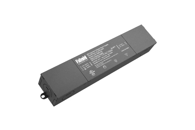
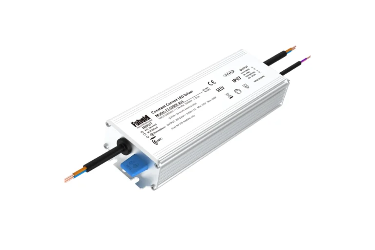
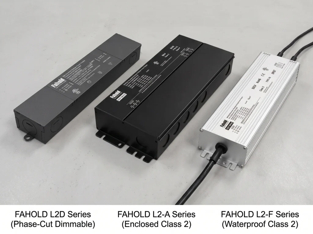
For a project using 100–120Vac and a compatible phase-cut wall control, FAHOLD L2D TRIAC / ELV / MLV Class 2 series is a practical starting platform. The series includes 12V/60W and 24V/60W variants and a 24V model class rated at 96W (24V × 4A). FAHOLD identifies Type B as the phase-cut dimming configuration; Type N is non-dimmable.
Do not specify L2D for a 277Vac supply. Its published rated input is 100–120Vac. For broader AC input requirements, compare a compatible L2-A or L2-F variant instead.
How Does 0–10V Dimming Work in Commercial LED Lighting?
A 0–10V system typically uses a separate low-voltage control circuit to convey the dimming command while AC power supplies the driver. Commercial lighting controllers use this arrangement because a number of fixtures can be assigned to an appropriate analog control zone without phase-cutting the power delivered to each driver.
What the separate 0–10V control pair does
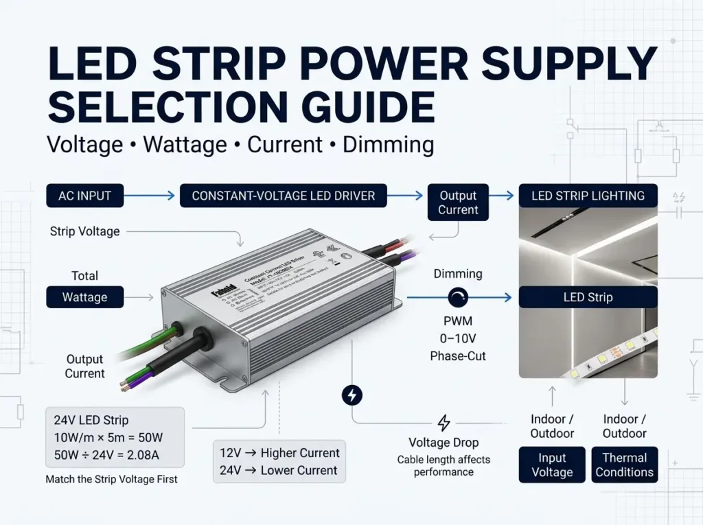
Think of the system as three distinct electrical paths: the rated AC input to the driver, the 0–10V control interface, and the regulated DC output to the LED strip. The analog signal is a control instruction, not a replacement for the 24V load supply and not a substitute for the AC feed.
A signal around 10V commonly represents the high end of the dimming range. The output at the low end is manufacturer- and interface-dependent; 0V may mean the lowest light setting rather than complete OFF. Driver curve, minimum current, controller setup and any independent switching relay can all matter.
Source versus sink: the overlooked check
In a widely used 0–10V implementation, the driver sources a small control current and the wall control or control module sinks it. Other interfaces use the opposite arrangement. If both devices expect to sink, or both expect to source, the pair may not behave properly. Control capacity also limits how many drivers one control channel can operate.
Lutron’s Application Note #587 on 0–10V control topology documents source/sink behavior, control ratings, dimming curves and OFF-state differences. Treat the controller specification and driver datasheet as a matched pair, even if both are labeled 0–10V.
Does 0–10V switch LEDs fully off?
Not necessarily. A low signal may simply request the driver’s minimum permitted brightness. Full OFF may require a control/driver combination explicitly supporting electronic OFF, or suitable line-voltage switching managed by the control system. Do not assume the phrase 0–100% dimming guarantees an extinguished LED load at 0V.
Before approval, test the expected minimum light level, actual OFF behavior, response after power restoration and whether multiple drivers on the same control zone behave consistently.
Where 0–10V is a strong fit
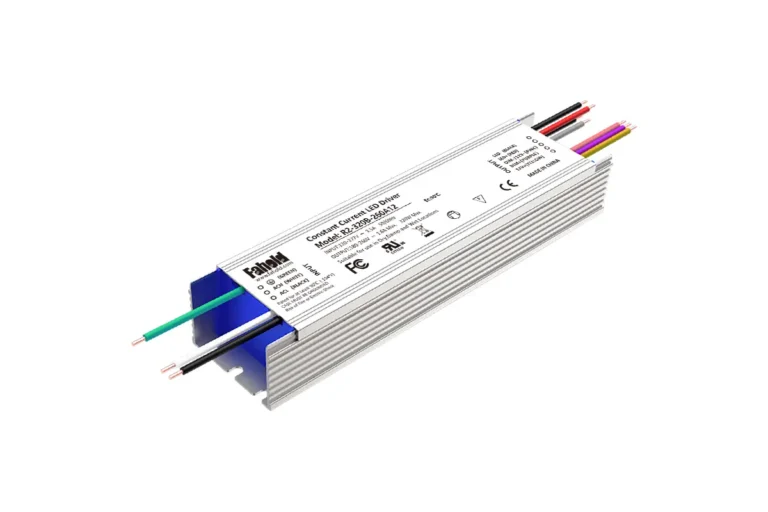
For offices, retail shelving, hospitality cove lighting and other projects already built around a 0–10V controller, prioritize a correctly configured multi-mode supply instead of retrofitting an AC phase-cut wall dimmer. FAHOLD L2-A enclosed Class 2 power supply platform includes 100–277Vac input and 12V/24V models with compatible 5-in-1 dimming options. Verify the specific control interface before assigning a model to a zone.
PWM Dimming: Control Signal vs LED Output Modulation
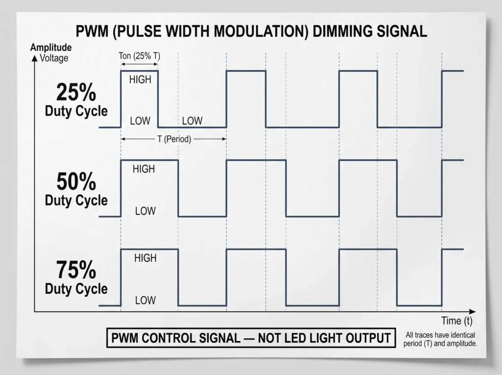
Pulse-width modulation (PWM) conveys a level by changing the fraction of a repeating cycle during which a signal is high. A 25% duty cycle means the signal is active for one-quarter of each period; 75% means it is active for three-quarters. This is a useful way to describe a control command, but it does not prove the LEDs will deliver precisely 25% or 75% of their full measured or perceived brightness.
How duty cycle can command brightness
Suppose a compatible controller produces a square-wave signal at a frequency accepted by the driver’s PWM input. When the duty cycle rises, the driver receives a request for a higher output level according to its implemented dimming curve. Response and low-end resolution depend on the driver—not simply the waveform.
Illustrative input signals:
| PWM command duty cycle | High portion of one period | Interpreted result |
|---|---|---|
| 25% | 1/4 | Lower brightness request |
| 50% | 1/2 | Intermediate brightness request |
| 75% | 3/4 | Higher brightness request |
The relationship between duty cycle and delivered luminous output must be confirmed for the selected driver. For the underlying electronics, see Analog Devices’ PWM LED-dimming explanation.
PWM input is not the same as PWM power output
There are at least two architectures a buyer can encounter:
- PWM command input on the driver: A controller sends a rated low-power signal; the driver interprets it and manages the LED supply internally.
- PWM power switching after a constant-voltage supply: A separate appropriately rated LED-strip controller switches the load current supplied by a DC source.
These arrangements differ in terminal ratings, driver responsibilities, system wiring and sometimes which components must be evaluated as part of the installed product. Never attach a power-switching LED strip output to a signal-only input unless the manufacturer’s instructions explicitly provide for that architecture.
PWM frequency, flicker and signal requirements
A PWM-compatible driver may specify allowable frequency, logic-high voltage, logic-low threshold, polarity, input impedance and isolation/reference requirements. A pulse train outside those limits may produce no response, erratic control or equipment damage. Low-frequency or deep-modulation operation can also create perceptible or camera-visible temporal light artifacts; a control input labeled PWM is not a universal promise of flicker-free LED output.
For lighting quality, assess representative fixtures using a suitable measurement method, particularly in hospitality, display and camera-sensitive spaces. Also confirm that the control signal is within the product’s stated input range; do not invent a universal PWM frequency or 5V/12V logic specification.
Appropriate PWM-based projects
PWM control may be useful for OEM lighting products that already have a compatible controller, specialized display systems and some architectural installations. FAHOLD lists PWM among the model-dependent control modes of its 5-in-1 dimmable LED power supplies. The exact model’s PWM input specification and validated controller pairing—not the series name alone—must determine final suitability.
Which Dimming Method Should You Choose for Your LED Project?
The best choice normally follows the controller that the installation already uses. A product that offers more dimming modes is not inherently better if the specified building system can use only one.
Existing wall dimmer: start with phase-cut compatibility
If the project already uses a 120Vac wall dimmer, record its exact model and phase setting. A Type B L2D model is a logical candidate if output voltage and loading also match. If the existing dimmer cannot be confirmed as compatible, a sample test is a requirement—not an optional finishing step.
Commercial lighting controls: evaluate 0–10V
For 0–10V building zones, identify the control module, source/sink relationship, rated number of drivers, required dimming curve and OFF method. Then choose a compatible configuration such as L2-A. The power supply’s 100–277Vac input range can be relevant for commercial 277Vac branches, but 277Vac compatibility does not automatically prove 0–10V performance with a particular controller.
PWM controller: verify the signal interface
For a PWM-controlled OEM assembly, obtain the controller waveform specification and the driver’s PWM input specification before evaluating any particular model. Confirm the project does not actually use a high-current PWM strip controller downstream of a conventional DC power supply.
Several interfaces: consider a 5-in-1 platform
If one manufacturer is building several fixtures for different customer controls, a platform supporting multiple dimming methods may reduce the number of basic supply designs to evaluate. That does not mean one device can accept every control signal simultaneously, or that all catalog suffixes and wattages support every option. Specify the required variant and control test in the purchase documentation.
| If the project says… | Check first | Product direction |
|---|---|---|
| “We already have a 120V forward-/reverse-phase wall dimmer.” | Dimmer exact model, phase mode, minimum load | L2D Type B |
| “Our building controller sends 0–10V and the circuit is 277V.” | Source/sink, OFF logic, control-zone capacity | L2-A compatible configuration |
| “Our outdoor lighting controller provides PWM commands.” | PWM logic/frequency, enclosure and splices | L2-F compatible configuration, after datasheet review |
| “We need flexibility for several North American projects.” | AC input, selected mode, certification and interface | L2-A / L2-F 5-in-1 platforms |
Three Class 2 Dimmable LED Power Supply Selection Examples
The cases below use illustrative connected LED loads, paired with published FAHOLD model ratings where those ratings are internally consistent. They are examples of a selection workflow, not evidence that a specific controller has been tested or approved with a particular driver.
Example 1: 120Vac wall-dimmer retrofit, 24V / 48W LED strip
Project: A hospitality millwork supplier is replacing an existing low-voltage strip power supply while retaining a compatible 120Vac phase-cut wall dimmer. The 24V strip assembly has a documented 48W maximum connected load.
Electrical sizing:
- Connected load: 48W at 24V = 2.0A nominal current.
- Candidate: L2D-060X-024, specified as 60W / 24V / 2.5A in FAHOLD current model table.
- Utilization: 48W ÷ 60W = 80%, before considering any required thermal derating or product-specific load restrictions.
- Required variant: Type B dimming configuration; do not use Type N if phase-cut dimming is required.
The main technical risk is not whether 60W exceeds 48W. It is whether the actual wall-dimmer model and selected L2D Type B variant work together across the desired dimming range. Confirm the dimmer phase, minimum loading, low-end trim, startup and true OFF behavior. The L2D’s stated 100–120Vac input also rules it out as a direct candidate for a 277Vac branch.
Recommended next action: review the L2D technical model table, request the Type B datasheet and test one sample with the specified dimmer.
Example 2: 277Vac commercial cove lighting, 24V / 72W at 0–10V
Project: A lighting contractor specifies a 24V constant-voltage LED cove lighting zone on a commercial 277Vac electrical system. The LED strip load is 72W and the zone is to follow the building’s 0–10V controller.
Electrical sizing:
- Connected load: 72W at 24V = 3.0A.
- Candidate: L2-100X-024A, a current FAHOLD L2-A model with 96W rated output, 24V / 4A, and 100–277Vac rated input.
- Utilization: 72W ÷ 96W = 75% before temperature and mounting-condition checks.
The candidate fits the example’s headline voltage and continuous current requirements. The remaining approval points concern its actual 0–10V-compatible configuration, source/sink behavior, 0V response, dimming curve, control wiring requirements and applicable listing. A 24V/96W nameplate alone says nothing about those controls.
The engineer should also check whether the building controller has a line-voltage switching mechanism or whether the project explicitly requires electronic OFF. An unexpectedly illuminated strip at the nominal 0V setting is a system-interface issue, not necessarily an output-power fault.
Recommended next action: compare the 96W L2-A model specifications with the exact building-controller documentation and request a configuration-specific sample.
Example 3: wet-location architectural lighting with a PWM controller
Project: A building-façade OEM plans a 24V lighting assembly in an environment where a waterproof power supply is needed. Its controller provides a defined PWM command signal. The preliminary LED load consists of two 24V zones rated at 30W each, or 60W total.
Initial calculations:
- Combined LED load: 30W + 30W = 60W.
- Nominal combined current: 60W ÷ 24V = 2.5A.
- Output architecture: either a permitted shared circuit or separate rated channels, subject to system and Class 2 requirements.
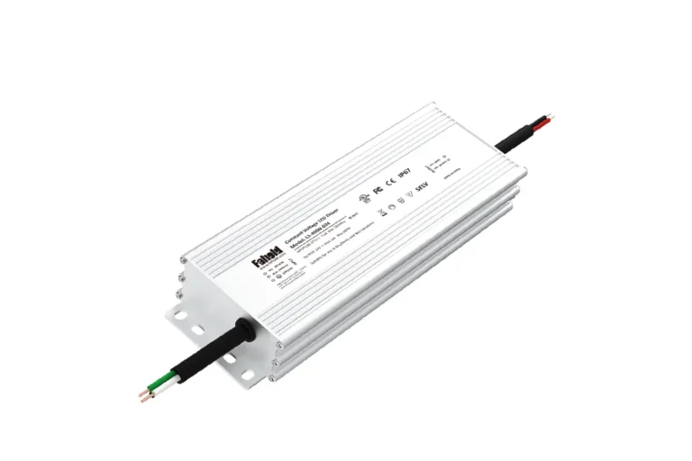
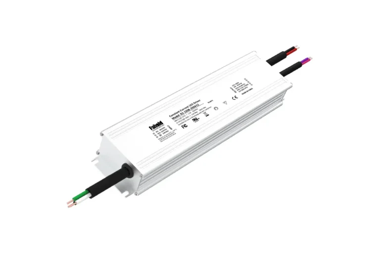
FAHOLD L2-F IP67 5-in-1 platform is worth evaluating because its overview lists waterproof construction, 24V versions and PWM as a model-dependent control option. Do not select a particular L2-F SKU from the published series-table current values alone. Some public L2-F rows show wattage, voltage and current figures that do not reconcile arithmetically; the signed-off manufacturer datasheet must settle the output rating and channel allocation before a recommendation is final.
The engineering review also needs the PWM waveform limits, controller compatibility, ingress protection of junctions and connectors, supply installation instructions, ambient-temperature rating and required certification for the final environment. IP67 enclosure performance is not proof that any arbitrary field connection is waterproof, nor is it proof of a particular Class 2 listing.
Recommended next action: provide FAHOLD the controller datasheet, zone diagram and environmental requirements to receive a verified L2-F configuration and appropriate test samples.
FAHOLD Class 2 Dimmable LED Power Supply Comparison
Different platforms should not be treated as interchangeable merely because they produce 24V DC. The installation voltage, dimming interface and enclosure requirement determine which family to investigate first.
| FAHOLD platform | Rated AC input | Constant-voltage output | Dimming direction | Installation consideration |
|---|---|---|---|---|
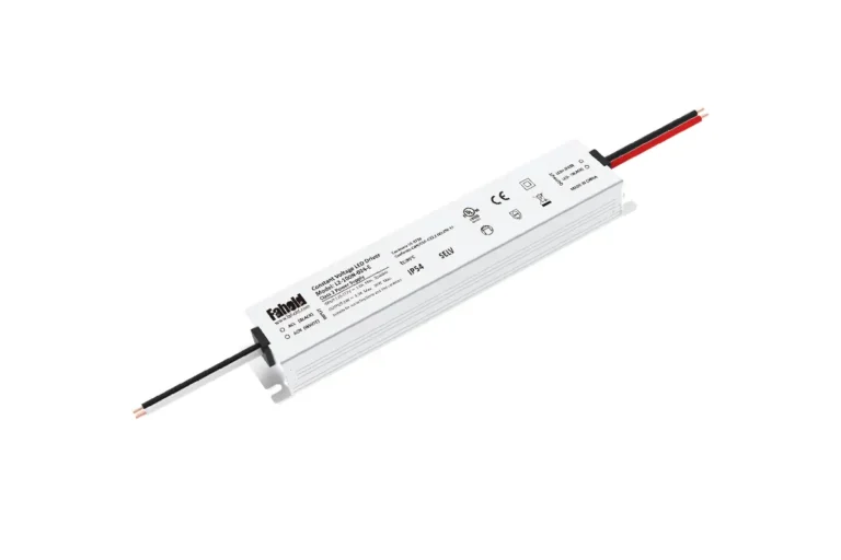
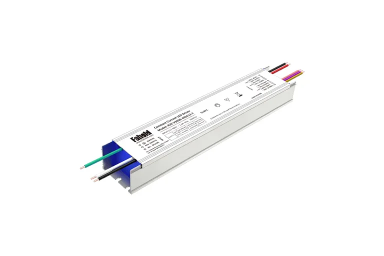
| L2D Type B | 100–120Vac | 12V/24V; 60W and 96W-rated options | TRIAC / ELV / MLV phase-cut | Integrated metal junction box; check compatible wall dimmer |
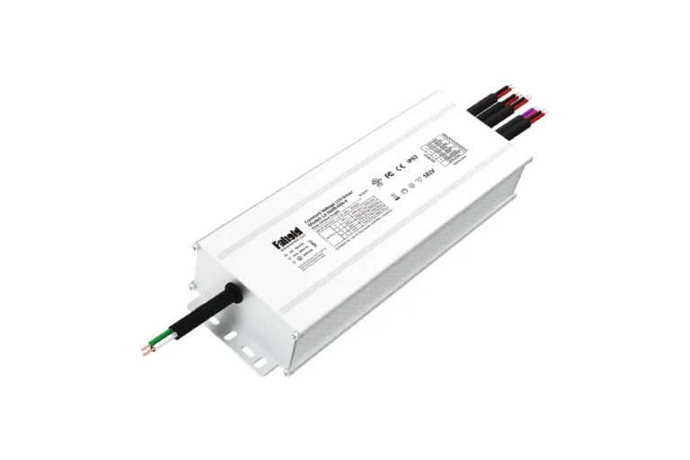
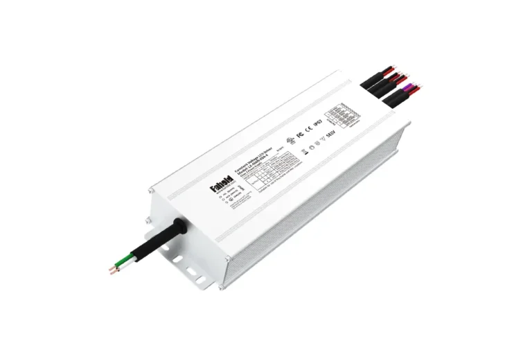
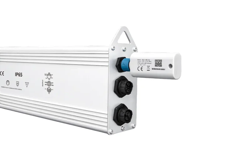
| L2-A compatible variant | 100–277Vac | 12V/24V; single- and multi-output models | Multi-mode / 5-in-1, including qualifying 0–10V and PWM options | Enclosed architectural platform; check selected control configuration |
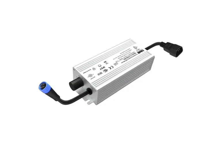
| L2-F compatible variant | 100–277Vac | 12V/24V; model-dependent channels | Multi-mode / 5-in-1, including qualifying PWM options | IP67 waterproof platform; verify corrected current/power specifications |
The table is a platform shortlist, not an approved compatibility chart or universal Class 2 certification statement. Request the datasheet and certification evidence for the exact model, variant and output circuit.
L2D: dedicated phase-cut projects
Choose this starting point when a 100–120Vac project uses a known compatible wall-dimming ecosystem. The comparatively focused model range simplifies initial selection, but compatible dimmer models and configuration suffixes still matter. Browse TRIAC / ELV / MLV dimmable LED drivers.
L2-A: enclosed architectural lighting with flexible controls
Choose an L2-A candidate when a project calls for 100–277Vac input and a specified 12V/24V dimming interface, especially in enclosed architectural installations. If multiple Class 2 output channels are needed, inspect the per-output ratings—not only the total product wattage. Browse FAHOLD L2-A models.
L2-F: IP67 multi-mode control
Choose L2-F for further evaluation where waterproof construction is a central requirement. Its published multi-mode capability is relevant, but both the exact PWM control interface and the corrected model electrical ratings must be approved before using a SKU in a design. Browse FAHOLD L2-F waterproof dimmable supplies.
Common Dimming Compatibility Problems and How to Avoid Them
Most dimming problems are system problems involving the control, power supply, loading and wiring together. Use symptom-based diagnosis instead of assuming the power supply has failed.
| Symptom | Possible cause | What to verify |
|---|---|---|
| Flickering near minimum brightness | Phase mode mismatch, minimum-load behavior, unstable PWM processing, or unsuitable dimming curve | Exact control model, driver load range, phase setting or PWM frequency, and a representative sample test |
| LEDs glow or flash after OFF | Controller leakage, driver low-end behavior, absence of actual mains switching | Manufacturer OFF-state specification, relay arrangement and controller compatibility |
| Dimmer moves but brightness is unchanged | Incorrect input terminal, incompatible source/sink behavior, unsupported PWM amplitude or mode | Separate control connection, driver configuration and input-signal specification |
| Different zones dim unevenly | Different driver models, loads, control curves, long control circuits or branch voltage drop | Model consistency, per-zone loading, shared control ratings and cable lengths |
| Buzzing at certain settings | Dimming waveform interacting with magnetic components or an incompatible load | Dimmer type, system loading and an approved dimmer/driver combination |
Flicker or unstable low-end dimming
Identify whether the symptom appears only at a low set point or throughout the range. For phase-cut systems, evaluate the dimmer’s documented minimum load and forward/reverse setting; for PWM systems, check the accepted pulse characteristics and possible temporal artifacts. Test under the same load and ambient conditions as the intended installation.
LEDs remain on or flash after switching off
“Dimmed to zero” and “electrically disconnected” are not necessarily the same state. Some 0–10V combinations need separate switching; some phase-cut systems may allow small currents through the control. Confirm the documented OFF method and do not improvise a wiring modification to correct it.
The control changes, but the LED level does not
First confirm the controller is delivering the kind of command the selected power supply accepts. A 0–10V analog level cannot be assumed to equal a PWM pulse input. Similarly, a phase-cut driver generally needs the appropriate dimmed AC feed, not only a separate signal wire.
Different LED zones do not track together
A single control channel may serve drivers with different dimming curves or response delays. Review control-zone loading, output ratings, LED-strip characteristics and the actual installed wire lengths. For a large project, document expected low, medium and high light settings and sample-test the complete group—not only one driver on a bench.
Get a 24V Class 2 Power Supply Configuration for Your Project
Share your LED load, branch layout, input voltage and installation requirements. FAHOLD can recommend a suitable single-output or multi-channel power supply for your technical review.
Need Help With Your LED Power Supply Project?
Tell us what you are working on. We will review your application and recommend the most relevant FAHOLD solution.
For North American Class 2 listing and full output architecture checks, use FAHOLD UL Class 2 selection guide. These system checks remain necessary even when a driver works correctly at 100% brightness.
Frequently Asked Questions
What is the difference between TRIAC and 0–10V LED dimming?
TRIAC/phase-cut dimming changes the AC input waveform reaching a compatible power supply. 0–10V usually sends a separate low-voltage analog command to a compatible driver while it continues to receive normal AC power. The required controller and connection architecture differ, so selecting between them starts with the project’s existing control system.
Can a TRIAC dimmer control a 0–10V LED driver?
Not directly, unless a specifically designed and appropriately rated interface converts the control method. A phase-cut wall dimmer is not inherently a 0–10V control source. Where a conversion interface is planned, its compatibility and installation requirements must be checked as part of the complete system.
Is PWM dimming better than 0–10V for LED strips?
Neither is universally better. A 0–10V interface may be a natural fit for a commercial building control network; PWM may suit an OEM controller that already provides an approved pulse command. PWM signal compatibility, temporal light artifacts, zoning and required wiring can matter more than the protocol label.
Can one Class 2 LED power supply support several dimming methods?
Yes, some multi-mode platforms support multiple accepted input-control methods, but only when the exact driver variant and wiring instructions allow them. “5-in-1” is not permission to apply all signals simultaneously. Verify the selected mode and model before use.
Why does a dimmable LED power supply flicker at low brightness?
Possible causes include a mismatch between the dimmer and driver, minimum-load constraints, unstable control behavior or LED-load interaction. PWM-related temporal effects can also contribute. Diagnose the complete controller–driver–load combination instead of assuming a single component is faulty.
Can I use a 0–10V Class 2 LED driver on 277V?
Only if that exact driver is rated for 277Vac input and supports the required 0–10V configuration. For example, the FAHOLD L2-A platform includes 100–277Vac versions, while L2D’s published rated input is 100–120Vac. The 0–10V command level is not the same as the building supply voltage.
How do I select a Class 2 dimmable power supply for 12V or 24V LED strips?
Match the LED strip’s rated 12V or 24V DC input, calculate its maximum watts/current, select an appropriate rated supply with any required thermal margin, verify each Class 2 output and then match the actual dimmer interface. Finally check environmental ratings, exact-model certification and sample-tested low-end performance.
Get Help Matching Your Dimmer and Class 2 LED Power Supply
Need a Class 2 LED power supply compatible with your dimming system? FAHOLD can review a project’s LED load, controller requirements and proposed installation conditions to help shortlist a suitable 12V/24V platform for technical validation.
For a useful recommendation, include:
- Controller/dimmer brand and exact model: identify whether it is phase-cut, 0–10V or PWM.
- Input supply and LED load: 120Vac or 277Vac; 12V/24V output; maximum connected load in watts.
- Output structure: single zone or separately rated multiple outputs.
- Control expectations: minimum brightness, OFF behavior, required compatibility tests.
- Environment: installation location, IP requirements, junction-box and wiring constraints.
- Procurement details: project country, estimated quantity, sample requirements and timing.
Request a Class 2 Dimming Compatibility Review and Project Quote
For model review, share the controller datasheet and load details. Final product approval must be based on the chosen configuration’s latest datasheet, certification record, and representative compatibility testing.