Table of Contents
Yes. Multiple LED strips can share one power supply when they use the same rated voltage and their combined load stays within the power supply’s usable output capacity.
For example, several 24V LED strips can be powered from one compatible 24V constant-voltage power supply. Their wattage and current must be added together, and the strips are normally distributed as parallel branches so that each branch receives the correct voltage.
The typical architecture is parallel distribution:
                         ┌── Branch A ── LED load
Power Supply (+V / -V) ──┼── Branch B ── LED load
                         └── Branch C ── LED load
Each compatible branch receives the same nominal source voltage, while branch currents add at the power supply.
The key sizing rule is:
The power supply must support the sum of all simultaneously operating branch loads, while each branch must be designed for its own current and voltage drop.
For the underlying architecture, see the Constant Voltage LED Power Supply Guide. For distribution-loss calculations, see Voltage Drop in Constant-Voltage LED Systems.
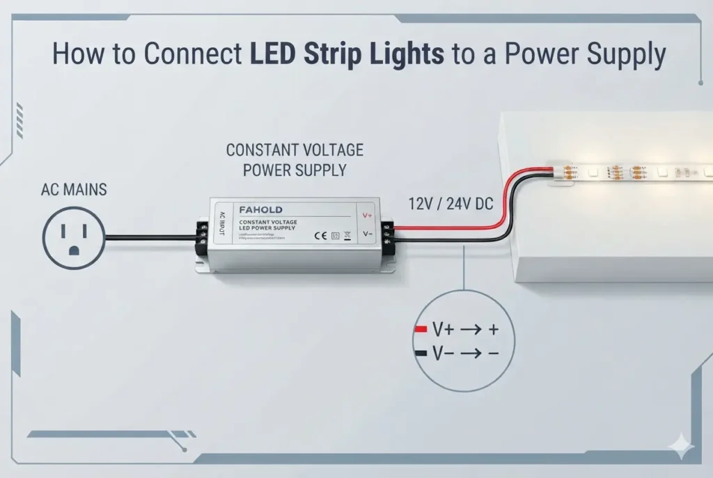
FAHOLD already has a practical guide explaining How to Connect LED Strip Lights to a Power Supply, including multiple-strip connection concepts.
Need to calculate the required power supply size?Use the LED Strip Power Supply Calculator.
Four Conditions Must Be True
1. Every directly connected load requires the same output voltage
A fixed 24V source can directly serve compatible 24V loads.
It cannot directly serve a mixture of conventional 12V and 24V loads.
2. The power supply supports the combined maximum load
Add all loads that can operate simultaneously.
3. Each branch is engineered separately
Each branch has its own current, length and voltage-drop condition.
4. The control and protection architecture supports the arrangement
Independent zones or small branch conductors fed from a high-capacity source may require additional design consideration.
Enough total watts alone do not prove the system is correct.
Why Constant-Voltage Loads Are Commonly Distributed in Parallel
Assume:
- system voltage: 24V;
- Branch A: 1.5A;
- Branch B: 2.0A;
- Branch C: 1.0A.
Total current:
1.5A + 2.0A + 1.0A = 4.5A
Nominal combined power:
24V × 4.5A = 108W
Each branch is connected across the nominal 24V source, subject to its own distribution voltage drop.
This is different from placing complete fixed-voltage loads in series, where source voltage is divided across the loads.
Can 3 LED Strips Share One Power Supply? A Worked Example
Assumptions
| Branch | Power | Current at 24V |
|---|---|---|
| A | 36W | 1.5A |
| B | 48W | 2.0A |
| C | 24W | 1.0A |
| Total | 108W | 4.5A |
Step 1 — Confirm common voltage
All loads require 24V.
Step 2 — Add total load
36W + 48W + 24W = 108W
Step 3 — Confirm total current
108W ÷ 24V = 4.5A
Step 4 — Evaluate the candidate supply
Do not stop at 108W.
The supply also needs:
- sufficient usable output under actual temperature/input conditions;
- compatible AC input;
- required dimming/control;
- suitable environmental rating;
- required certification;
- acceptable dimensions.
For capacity margin, continue with How Much Power-Supply Capacity Should You Leave for LED Loads?.
f you already know the strip voltage, watts per meter and total run length, use the LED Strip Power Supply Calculator to estimate the required power-supply capacity.
Multiple LED Loads Are Not the Same as Paralleling Power Supplies
There is a critical distinction.
One supply feeding several loads
One power supply serves several compatible branches.
This is the topic of this article.
Several power-supply outputs tied together
Two or more power supplies are electrically paralleled to increase current or build another power architecture.
Do not assume this is permitted just because the voltage labels match.
MEAN WELL’s technical FAQ states that parallel connection requires compatible functions, close output-voltage/wiring matching and specified wiring practice. It also notes that LED power supplies without parallel current-sharing function are not generally suitable for simply tying outputs together: MEAN WELL — Parallel-Connection Requirements.
Practical rule:
Only parallel power-supply outputs when the exact manufacturer documentation explicitly permits it and provides the method.
Can 12V and 24V LED Strips Share the Same Power Supply?
No. Conventional 12V and 24V LED strips should not be connected directly to the same fixed-voltage power-supply output because each load must receive its rated voltage.
Potentially compatible on one fixed output:
- 24V strip;
- 24V strip;
- 24V signage module.
Not directly compatible on one fixed output:
- 12V strip;
- 24V strip.
Do not choose the common voltage from total wattage.
If architecture is unclear, see What Is a Constant Voltage LED Power Supply? and Constant Voltage vs Constant Current for LED Lighting.
Main-Feed Current and Branch Current Are Different
The supply sees the combined current.
Each branch carries its branch current.
Using the previous example:
- main feed before the split: approximately 4.5A under the stated load;
- Branch A: 1.5A;
- Branch B: 2.0A;
- Branch C: 1.0A.
A conductor adequate for a 1A branch may not be appropriate for a 4.5A trunk.
Southwire’s professional voltage-drop calculator evaluates conductor sizing from current, cable-run length, voltage-drop target and ampacity constraints: Southwire Re³ Voltage Drop Calculator.
Why Daisy-Chained Power Paths Can Create Problems
The word “daisy chain” is used inconsistently, so focus on the real current path.
A problematic arrangement occurs when downstream-load current must pass through upstream wiring, connectors or strip traces that were not intended to carry the combined current.
That can increase:
- voltage drop;
- connector loading;
- dependence on upstream connections;
- brightness differences between near and remote loads.
Dedicated parallel feeds or engineered distribution points are generally easier to calculate and troubleshoot.
Equal Loads Can Still Have Unequal Brightness
Assume two identical 24V branches:
- Branch A conductor run: 5 ft;
- Branch B conductor run: 40 ft.
Even though the LED loads are identical, the longer branch can have more conductor resistance and therefore more voltage drop.
The correct response is not automatically to install a larger-wattage supply.
Instead check:
- branch current;
- conductor length;
- conductor size;
- connector resistance;
- LED product run/feed instructions.
See Voltage Drop in Constant-Voltage LED Systems for the detailed diagnostic process.
Parallel Branches vs Power Injection
Parallel branch
A dedicated pair of conductors feeds a separate load or load section from a distribution point.
Power injection
An additional connection feeds another point along a longer LED load to reduce the effective current path through wiring or strip traces.
Both still contribute to total supply load.
Do not publish a universal instruction such as “inject every 5 meters.”
The correct feed method depends on the exact LED product’s voltage, watts per foot/meter, maximum run length, copper construction and manufacturer instructions.
For strip-specific selection, use How to Choose the Right Power Supply for LED Strip Lights.
One Central Power Supply vs Several Distributed Supplies
Neither architecture is universally better.
| Design issue | One centralized supply | Several distributed supplies |
|---|---|---|
| Low-voltage cable distance | Can be longer | Often shorter |
| Service point | Centralized | Multiple locations |
| Branch current | May concentrate in trunk | More localized |
| Voltage drop | Requires deliberate distribution | Can be easier to control |
| Independent zones | Needs control planning | Can be easier |
| Failure impact | May affect more loads | More localized |
| AC distribution | Centralized | Requires AC in more locations |
For LED Strip Lighting and Sign Lighting, physical layout can be as important as total wattage.
Dimming and Control Zoning
A multi-load system needs a control architecture as well as a power architecture.
Ask:
- Do all branches dim together?
- Do branches need independent zones?
- Is the controller upstream or downstream of the DC source?
- What is the controller’s output-current limit?
- Does the power supply support the required interface?
For DALI systems, the DALI Alliance identifies LED drivers as control gear within a defined system that also includes application controllers and input devices: DALI Alliance — DALI-2 Systems and Components.
This reinforces a broader rule: DC branch wiring alone does not define the control topology.
Protection Becomes More Important as One Source Gets Larger
A high-capacity source can feed several smaller downstream conductors.
Do not invent a generic branch fuse size.
Protection decisions should follow:
- exact power-supply instructions;
- conductor ampacity;
- connected equipment instructions;
- branch architecture;
- applicable code;
- listing/system requirements.
UL Solutions discusses UL 2108 as the Standard for Low Voltage Lighting Systems in relevant North American applications: UL Solutions — UL 2108 Low-Voltage Lighting Systems.
Where signs are involved, applicable sign-system requirements should also be verified for the actual product and installation.
Example: Three Architectural Cove Runs
Assumptions
- voltage: 24V;
- Run A: 40W;
- Run B: 55W;
- Run C: 35W.
Combined load:
40W + 55W + 35W = 130W
Combined current:
130W ÷ 24V ≈ 5.42A
A real design review should then ask:
- Are all three loads actually rated 24V?
- Is 130W the maximum simultaneous load?
- What usable output remains after applicable derating?
- How much current flows through the trunk before branching?
- How long is each branch?
- What conductor size is required?
- Are product-specific strip run limits respected?
- Do all branches share one dimming zone?
- What environmental and certification requirements apply?
Only after these conditions are known is exact power-supply matching defensible.
Example: Multi-Branch Sign Lighting
Signage often contains many LED modules distributed through a cabinet or channel-letter system.
Record:
- modules per branch;
- watts/current per branch;
- total simultaneous load;
- longest DC run;
- remote branch voltage;
- environmental conditions;
- service access.
For application-specific context, see Sign Lighting.
Multi-Load Design Workflow
Step 1 — Confirm load architecture
Verify that the loads are compatible constant-voltage devices.
Step 2 — Confirm one common voltage
Every directly connected load must support the source voltage.
Step 3 — Calculate each branch
Record watts and current separately.
Step 4 — Add the maximum simultaneous load
This establishes source capacity.
Step 5 — Draw the distribution topology
Show trunk, branch points, controllers, injection points and load locations.
Step 6 — Calculate voltage drop per path
The longest path is not always the worst path; current matters too.
Step 7 — Confirm control zones
Independent branches may require separate controllers or channels.
Step 8 — Determine conductor and protection requirements
Follow equipment instructions and project requirements.
Step 9 — Check environment and temperature
Enclosed signs and architectural cavities can change usable power-supply capacity.
Step 10 — Select the exact supply
At this stage the project contains enough information for defensible product matching.
Choosing a FAHOLD Power Supply for Multiple LED Strip Loads
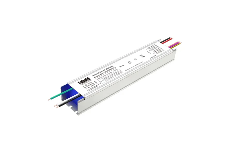
Once the output voltage, combined load, wiring layout and dimming method are known, the next step is matching the project to the appropriate constant-voltage power-supply platform.
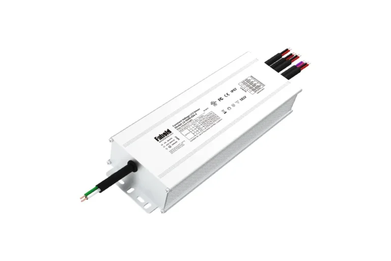
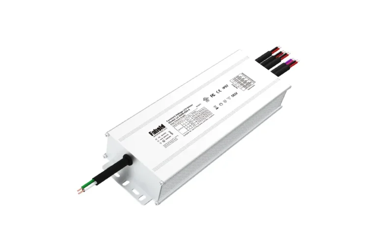
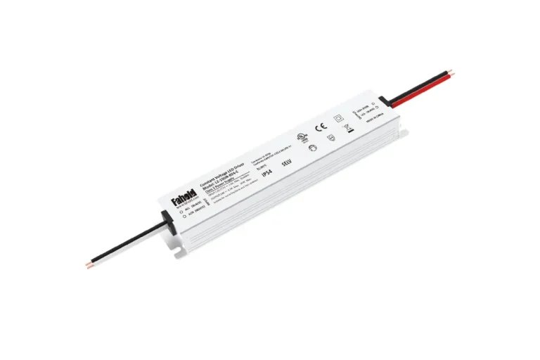
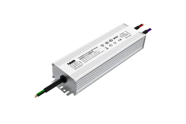
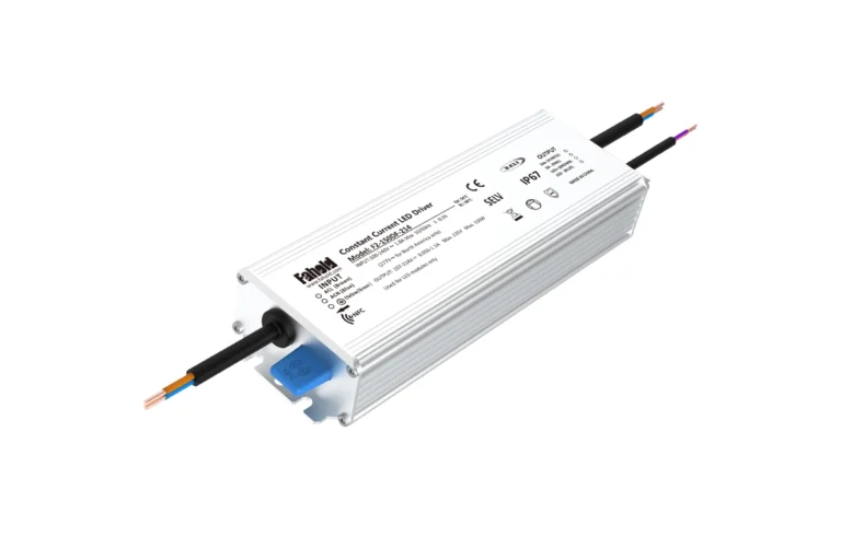
FAHOLD L2-A Series is suitable for architectural and commercial LED strip projects requiring 100–277Vac input and flexible 5-in-1 dimming. The series includes 12V and 24V constant-voltage configurations for different project loads.View L2-A Series →
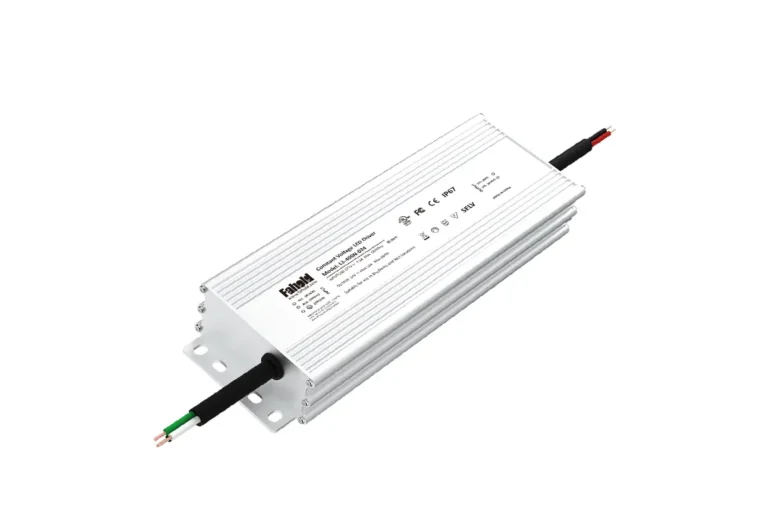
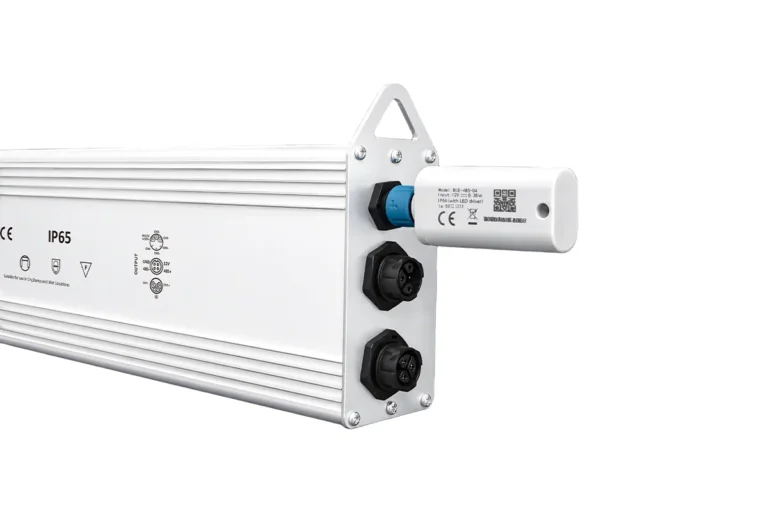
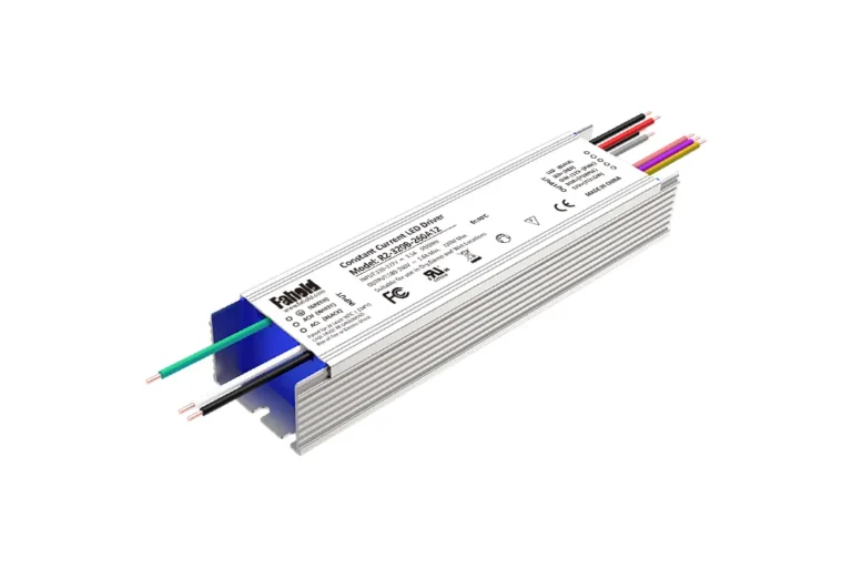
FAHOLD L2-F Series is another option for architectural LED strip installations where a waterproof power-supply platform and flexible dimming integration are required.View L2-F Series →
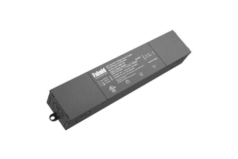
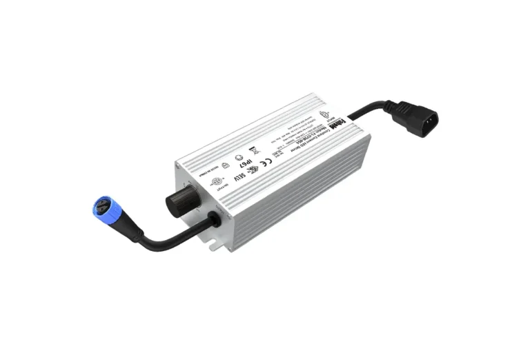
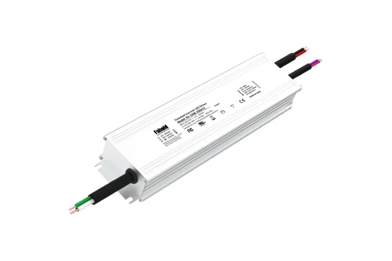
FAHOLD L2D Series is designed for 100–120Vac phase-cut applications and is relevant when the LED strip system must work with TRIAC, ELV or MLV dimming.View L2D Series →
The final model should be selected from the actual output voltage, maximum simultaneous wattage, control method, installation environment and certification requirements.
Information to Send FAHOLD
| Requirement | Information |
|---|---|
| Market | US / Canada / other |
| AC input | Project requirement |
| Output voltage | 12V / 24V / 48V / other |
| Branch count | Number of loads/zones |
| Branch power | W or A per branch |
| Total load | Maximum simultaneous watts |
| Longest DC run | Distance |
| Control | None / 0–10V / DALI / phase-cut / other |
| Environment | Indoor / outdoor / enclosed |
| Certification | Project-specific |
| Dimensions | Available installation space |
Then contact FAHOLD for specification-based matching.
LED Strips Power Supply FAQ
Can multiple LED strips use one power supply?
Yes, when they require the same voltage and the source, conductors, controls and protection are designed for their combined maximum load.
Should constant-voltage LED strips be wired in parallel?
Parallel distribution is commonly used so compatible strip branches receive the required source voltage. Follow the exact product wiring instructions.
How do I size one power supply for three strips?
Add the maximum wattage of all three strips, calculate total current at the common voltage, then verify usable supply capacity, derating and branch distribution.
Can I connect two 24V power supplies together for more power?
Only when the exact supplies explicitly support parallel operation and the manufacturer provides the approved connection method.
Why is one LED strip dimmer than another?
Different branch current, conductor length, conductor size, connectors or strip resistance can create different voltage drop.
Is one large supply better than several smaller supplies?
Not universally. Compare DC run length, zoning, serviceability, branch current, AC distribution and failure impact.
Do I need separate protection for every branch?
That depends on the source, conductors, equipment instructions, listing and applicable project requirements. Do not use a generic fuse size without system-specific data.
Need Help With Your LED Power Supply Project?
Tell us what you are working on. We will review your application and recommend the most relevant FAHOLD solution.