Table of Contents
Choosing a power supply for LED strip lights is not just a wattage calculation.
For a typical low-voltage strip system, a commercial LED strip power supply must match the strip’s electrical architecture, rated voltage, total load, current demand, wiring layout, dimming method, environmental conditions, and target-market requirements.
The basic workflow is:
- Confirm the LED strip is a constant-voltage load.
- Match the strip voltage.
- Calculate total wattage.
- Calculate required output current.
- Check usable power-supply capacity and derating.
- Design the wiring and feed points.
- Check voltage drop and power-supply distance.
- Define the dimming/control architecture.
- Verify environment and safety requirements.
- Troubleshoot the complete system rather than blaming the power supply for every symptom.
For most conventional 12V and 24V LED strips, this means selecting a compatible constant-voltage LED power supply.
If you need the broader electrical framework first, see the Constant Voltage LED Power Supply Guide. If you need a detailed step-by-step product-selection workflow, continue to How to Choose the Right Power Supply for LED Strip Lights.
LED Strip Power Supply Requirements: Quick Reference
LED strip power supply requirements depend on the strip voltage, rated power consumption, powered length, output current, wiring layout, dimming method, and installation conditions.
| Selection Item | What to Confirm |
|---|---|
| Load architecture | Constant voltage or another specified architecture |
| Strip voltage | 12V / 24V / 48V / other specified value |
| Strip power | W/ft or W/m |
| Total length | Total powered length and length per feed |
| Total wattage | Maximum simultaneous load |
| Output current | Total W ÷ system V |
| Power-supply capacity | Sufficient usable output after applicable derating |
| Wiring | Conductor size, distance, branch layout |
| Voltage drop | Acceptable at the remote load |
| Dimming | PWM / 0–10V / DALI / phase-cut / other as specified |
| Environment | Indoor / enclosed / damp / outdoor |
| Safety/compliance | Project- and market-specific |
| Mechanical fit | Driver dimensions, terminals, mounting |
1. What Type of Power Supply Does an LED Strip Need?
Many conventional low-voltage LED strips are designed to operate from a fixed DC voltage.
Typical labels may show:
- 12VDC;
- 24VDC;
- 48VDC;
- watts per foot or meter.
For these applications, the external power source is normally a constant-voltage LED strip power supply designed to maintain the required 12V, 24V, 48V or other specified DC output.
The supply regulates the system voltage while the compatible LED strip draws current according to its design and connected length.
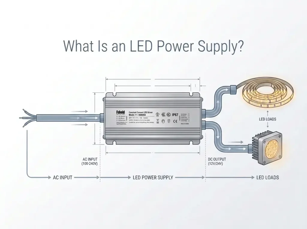
A typical architecture is:
AC Mains
   ↓
Constant-Voltage LED Power Supply
   ↓
12V / 24V / 48V DC
   ↓
LED Strip
If a controller is used:
AC Mains
   ↓
Constant-Voltage LED Power Supply
   ↓
LED Controller
   ↓
LED Strip
Do not choose constant voltage merely because the load looks like an LED strip. Confirm the exact product label or datasheet.
IEC 61347-2-13:2024 is the current IEC safety standard covering electronic controlgear for LED light sources and reinforces the importance of defined rated output characteristics: IEC 61347-2-13:2024.
For the CV/CC distinction, use the Constant Voltage LED Power Supply Guide.
2. Match the LED Strip Voltage First
The first hard compatibility check is the strip voltage.
A conventional:
- A conventional 12V strip requires a compatible 12V LED strip power supply, while a 24V strip requires a compatible 24V LED strip power supply. In both cases, the power supply must provide the correct constant-voltage output before wattage or current capacity is considered.48V strip requires a compatible 48V output where that strip is designed for 48V.
A power supply with enough wattage but the wrong output voltage is still the wrong power supply.
Why voltage changes current
For a simplified DC load:
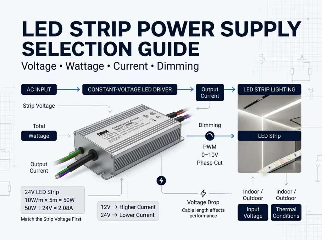
Current (A) = Power (W) ÷ Voltage (V)
For a 120W load:
| System Voltage | Approximate Current |
|---|---|
| 12V | 10A |
| 24V | 5A |
| 48V | 2.5A |
Higher system voltage reduces current for the same power.
That can affect:
- conductor sizing;
- voltage drop;
- connector loading;
- power-distribution architecture.
But this does not mean the highest voltage is always better.
The LED strip itself must be designed for the selected voltage.
For the dedicated strip-level comparison, see 12V vs 24V LED Strip: Which Voltage Should You Use?.
3. Calculate LED Strip Power Consumption and Power Supply Wattage
Once voltage is confirmed, calculate the maximum connected load.
For strip rated in watts per meter:
Total Load (W) = Strip Power (W/m) × Powered Length (m)
For strip rated in watts per foot:
Total Load (W) = Strip Power (W/ft) × Powered Length (ft)
Example
Assume:
- strip voltage: 24V;
- strip power: 9.6W/m;
- powered length: 8m.
Calculation:
9.6W/m × 8m = 76.8W
The nominal LED load is therefore 76.8W.
The next step is not simply to buy the nearest power supply whose label exceeds 76.8W.
You still need to check:
- maximum simultaneous load;
- usable supply output;
- temperature and input-voltage derating;
- current capacity;
- wiring;
- dimming;
- environment.
For the calculation-focused child page, use How to Calculate Power Supply Wattage for LED Strips.
4. Calculate the Required Output Current
For a constant-voltage strip system:
Current (A) = Total Power (W) ÷ Output Voltage (V)
Using the 76.8W, 24V example:
76.8W ÷ 24V = 3.2A
The selected supply therefore needs to provide:
- the correct 24V output;
- enough usable output-current capacity for the complete load.
This current value also becomes important for:
- controller sizing;
- conductor sizing;
- voltage-drop calculations;
- connector and terminal loading.
A system can have “enough watts” while still being poorly designed if its current paths are ignored.
5. Do Not Apply a Universal 20% Power Rule
Many LED-strip guides automatically recommend adding 20% to every load calculation.
That can be a useful preliminary planning shortcut, but it should not be presented as a universal legal or engineering requirement.
A better process is:
- Calculate the maximum LED load.
- Review the candidate supply’s allowed continuous loading.
- Check temperature and input-voltage derating.
- Identify any project-specific reliability or expansion margin.
- Select the appropriate standard rating.
For the dedicated discussion of rated capacity, derating, usable capacity, and planning margin, see How Much LED Power Supply Headroom Should You Leave?.
This separation is important because a power supply can look comfortably oversized on its nameplate while having much less usable capacity under high-temperature or low-input conditions.
6. Wiring: Think in Terms of the Complete Power Path
The power supply is only one part of the electrical path.
A typical single-color strip system includes:
AC Input
   ↓
LED Power Supply
   ↓
DC Cable
   ↓
Optional Controller
   ↓
LED Strip
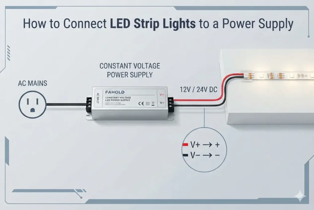
For detailed terminal identification, polarity, AC/DC separation, controller placement, and connection examples, use How to Connect LED Strip Lights to a Power Supply.
Safety boundary
The low-voltage DC output side and the AC mains input side are not equivalent.
Work on exposed energized mains circuits creates serious electrical hazards. OSHA’s general-industry electrical work-practice requirements state that only qualified persons may work on electric circuit parts or equipment that have not been de-energized under the required procedures: OSHA 29 CFR 1910.333 — Selection and Use of Work Practices.
Installation must also follow the exact power-supply instructions and applicable local electrical requirements.
7. Multiple LED Strips: Add the Loads, Then Design the Branches
There is no fixed answer to:
“How many LED strips can one power supply run?”
The limit depends on the complete system.
For three compatible 24V branches:
| Branch | Load |
|---|---|
| A | 30W |
| B | 42W |
| C | 24W |
| Total | 96W |
Total current:
96W ÷ 24V = 4A
The supply must support the combined maximum load, but the distribution system must also support:
- main-feed current;
- branch current;
- branch voltage drop;
- controller capacity;
- connector loading.
For the dedicated article, see How Many LED Strips Can One Power Supply Run?.
Do not confuse one supply feeding several LED branches with electrically paralleling several power-supply outputs. Those are different architectures, and power-supply paralleling requires explicit manufacturer support.
8. Voltage Drop: Why a Correct Power Supply Can Still Produce a Dim Far End
Voltage drop occurs when current flows through resistance in:
- wire;
- connectors;
- terminals;
- PCB traces;
- LED-strip copper paths.
The simplified relationship is:
Vdrop = I × R
A power supply can measure the correct voltage at its terminals while a distant strip receives a lower voltage.
Symptoms may include:
- lower brightness at the far end;
- brightness differences between branches;
- color variation;
- unstable operation.
Southwire’s professional voltage-drop calculator determines conductor size or voltage drop from current, run length, conductor size, and circuit conditions: Southwire Re³ Voltage Drop Calculator.
For the LED-strip-specific issue, see LED Strip Voltage Drop Explained: Causes and Solutions.
9. How Far Can the Power Supply Be From the LED Strip?
There is no universal maximum distance.
The practical distance depends on:
- system voltage;
- load current;
- conductor size;
- conductor material;
- allowable voltage drop;
- branch architecture;
- connectors;
- the strip’s own electrical design.
This is why a statement such as:
“A 24V power supply can always be 50 feet from the strip”
is not technically defensible without additional conditions.
The correct method is to calculate the specific distribution path.
For the dedicated distance article, see How Far Can a Power Supply Be From LED Strip Lights?.
10. Power Injection and Feed Points
Long LED-strip installations may require additional feed points.
Possible architectures include:
- one-end feed;
- center feed;
- dual-end feed;
- multiple injection points;
- separate parallel branches.
The correct method depends on the exact strip design and manufacturer instructions.
Do not use a universal rule such as “inject power every 5 meters.”
A strip with higher W/m, narrower copper traces, lower operating voltage, or different segment architecture may require a different feed strategy.
Power injection also does not reduce the total load. The power supply still needs enough usable capacity for the complete LED system.
11. Dimming: Match the Entire Control Architecture
“Dimmable LED strip power supply” can describe several different system architectures.
In commercial projects, a dimmable LED strip power supply should be selected from the actual control architecture rather than from the word “dimmable” alone. An 0–10V dimmable LED strip power supply must match the project’s 0–10V control interface, while a TRIAC dimmable LED strip power supply must be compatible with the selected phase-cut dimmer and load conditions.
For architectural LED strip installations, the required control method should therefore be defined before the exact power-supply series is selected.
The most common distinction is whether dimming occurs:
- inside the power supply/driver;
- in a downstream LED controller;
- through an upstream phase-cut control;
- through a wired control interface such as 0–10V or DALI;
- through PWM on the DC side, depending on the system design.
These methods are not interchangeable.
Downstream PWM control
A common constant-voltage architecture is:
AC Mains
   ↓
Constant-Voltage Power Supply
   ↓
PWM LED Controller
   ↓
LED Strip
The power supply provides the required DC voltage while the downstream controller switches or modulates the LED-strip output.
Driver-integrated dimming
Some power supplies include their own dimming/control interface.
The exact product documentation must then confirm:
- supported control method;
- control wiring;
- output behavior;
- load requirements;
- controller compatibility.
For DALI systems, the DALI Alliance defines LED drivers as control gear within the DALI control architecture, alongside application controllers and input devices: DALI Alliance — DALI-2 Systems and Components.
For the dedicated strip-level dimming guide, see How to Dim LED Strip Lights With the Right Power Supply.
For PWM specifically, continue to PWM Dimming for LED Strip Power Supplies.
12. PWM, 0–10V, DALI and Phase-Cut Are Different Questions
These terms often appear together in product searches, but they describe different control approaches.
| Control Method | What Must Be Verified |
|---|---|
| PWM on DC side | Controller voltage, channel current, total load, strip compatibility |
| 0–10V | Driver/control-input compatibility and wiring |
| DALI | DALI control gear/system compatibility |
| Phase-cut | Driver compatibility with the selected leading/trailing-edge control method |
| Non-dimming | No control interface required beyond switching |
The important procurement rule is:
Do not choose a power supply because the product page simply says “dimmable.” Verify the exact control interface and system topology.
This is particularly important when replacing an existing driver because two dimmable units with identical wattage and output voltage may use different control methods.
13. Indoor, Enclosed and Outdoor Installations Need Different Checks
LED-strip applications can range from an open indoor shelf to an outdoor architectural profile.
Before selecting the power supply, identify whether it will be installed:
- in open indoor air;
- inside an enclosure;
- in a ceiling or architectural cavity;
- in a damp location;
- outdoors with indirect exposure;
- outdoors with direct environmental exposure.
The environment can affect:
- thermal performance;
- required enclosure protection;
- wiring method;
- corrosion exposure;
- product lifetime;
- usable output capacity.
Do not choose an IP rating from a generic application label alone.
The exact power supply, enclosure design, installation method and project requirement must be considered together.
Searches for a waterproof LED strip power supply or outdoor LED strip power supply usually indicate that the installation requires additional environmental protection, but “outdoor” alone is not enough to select a product. Verify the required IP rating, exposure conditions, enclosure design, operating temperature and wiring method for the actual project.
14. Thermal Derating Can Change the Required Power-Supply Rating
A power supply’s nameplate wattage is not always equal to the usable output under every operating condition.
Manufacturers may specify reduced output at:
- elevated ambient temperature;
- low AC input voltage;
- certain mounting or cooling conditions.
That means a 100W LED load does not necessarily mean that every 100W-labeled supply is suitable.
The correct process is:
- calculate the maximum load;
- identify the installation temperature/environment;
- check the exact supply’s derating curves;
- establish usable output;
- add any justified project margin.
For the detailed headroom/derating methodology, see How Much LED Power Supply Headroom Should You Leave?.
15. North American Low-Voltage Lighting: Do Not Assume Class 2 From Voltage Alone
A 12V or 24V system is low voltage, but that does not automatically mean every power supply or complete installation can be described as Class 2.
UL 2108 covers low-voltage lighting systems and includes power units, Class 2 configurations, and other low-voltage lighting systems within its scope. The current UL Standards & Engagement page identifies UL 2108 as an active standard for systems installed in accordance with NEC Article 411: UL 2108 — Low Voltage Lighting Systems.
For North American procurement, verify:
- the exact power-supply certification/listing;
- output limits;
- complete system architecture;
- applicable product/system standard;
- project requirements.
Do not convert “24V” into an unsupported “Class 2” marketing claim.
A Class 2 LED strip power supply may be required for some North American low-voltage lighting projects, but a 24V Class 2 LED power supply cannot be identified from output voltage alone. The exact power unit, output limits, certification/listing and complete system configuration must satisfy the applicable project requirements.
16. LED Strip Power Supply Troubleshooting
A useful troubleshooting process starts by identifying which part of the system is failing.
Symptom 1 — The LED strip does not turn on
Check:
- AC input is present;
- the power supply is receiving the correct input;
- DC output voltage is present;
- output voltage matches the strip;
- polarity is correct;
- controller wiring is correct;
- connectors/terminals are secure;
- protection has not activated.
For detailed wiring checks, use How to Connect LED Strip Lights to a Power Supply.
Symptom 2 — The far end is dimmer
Likely investigation areas include:
- excessive strip length on one feed;
- conductor voltage drop;
- inadequate feed points;
- high-resistance connectors;
- unsuitable system voltage for the distribution design.
See LED Strip Voltage Drop Explained and How Far Can a Power Supply Be From LED Strip Lights?.
Symptom 3 — The strip flickers
Flicker can have several causes.
Potential areas include:
- overload or protection cycling;
- loose connections;
- incompatible dimming;
- controller problems;
- supply/input instability;
- LED-strip or connector faults.
Do not assume all flicker is caused by the power supply.
For the dedicated fault-isolation workflow, see Why Do LED Strips Flicker? Power-Supply Troubleshooting Guide.
Symptom 4 — One branch works but another does not
Check the affected branch independently:
- branch voltage;
- branch current;
- polarity;
- connector continuity;
- controller channel;
- branch-specific voltage drop.
This often points to a distribution or connection problem rather than insufficient total source wattage.
17. Common LED Strip Power-Supply Mistakes
Mistake 1 — Choosing watts before voltage
A 200W 12V supply is still wrong for a conventional 24V strip.
Mistake 2 — Treating every LED load as constant voltage
Confirm the actual load specification.
Mistake 3 — Applying one universal headroom percentage
Use actual load plus the candidate power supply’s operating/derating requirements.
Mistake 4 — Ignoring current
Current matters for:
- conductors;
- controllers;
- terminals;
- voltage drop.
Mistake 5 — Assuming one power supply can feed unlimited strip length
Total wattage is only one limitation.
The distribution path and the strip’s own maximum-run design can become limiting first.
Mistake 6 — Solving voltage drop by installing a higher-wattage supply
Extra source capacity does not automatically reduce conductor resistance.
Mistake 7 — Assuming “dimmable” means compatible
The dimming/control method must match.
Mistake 8 — Treating indoor ambient temperature as enclosure temperature
A power supply inside a closed cabinet can experience very different thermal conditions.
Mistake 9 — Selecting the product before defining the complete load
The LED strip system should define the power-supply specification—not the reverse.
18. LED Strip Power Supply Selection Workflow
Use the following sequence for a new commercial or OEM project.
Step 1 — Identify the LED strip
Record:
- voltage;
- W/m or W/ft;
- maximum run/feed instructions;
- strip type;
- dimming/control requirements.
Step 2 — Determine total powered length
Separate:
- total project length;
- length per branch/feed.
These are not always the same.
Step 3 — Calculate total maximum load
Use the LED-strip manufacturer’s rated power data.
Step 4 — Calculate output current
I = P ÷ V
Step 5 — Check candidate usable capacity
Review:
- continuous loading;
- thermal derating;
- input-voltage derating.
Step 6 — Draw the distribution topology
Identify:
- power-supply location;
- controller location;
- trunk conductors;
- branch conductors;
- injection/feed points.
Step 7 — Evaluate voltage drop
Calculate the relevant current paths rather than using a fixed maximum-distance rule.
Step 8 — Define dimming and zoning
Confirm:
- control method;
- number of zones;
- controller current;
- power-supply compatibility.
Step 9 — Define installation environment
Indoor, enclosed, damp or outdoor.
Step 10 — Verify market and compliance requirements
For North America, check the exact project/listing requirements instead of assuming Class 2 from voltage alone.
Step 11 — Check dimensions and serviceability
The correct electrical specification still has to fit the physical project.
Step 12 — Select the exact supply
Only after the load and installation are defined should a specific series/model be selected.
18. LED Strip Power Supply Options for Commercial Projects
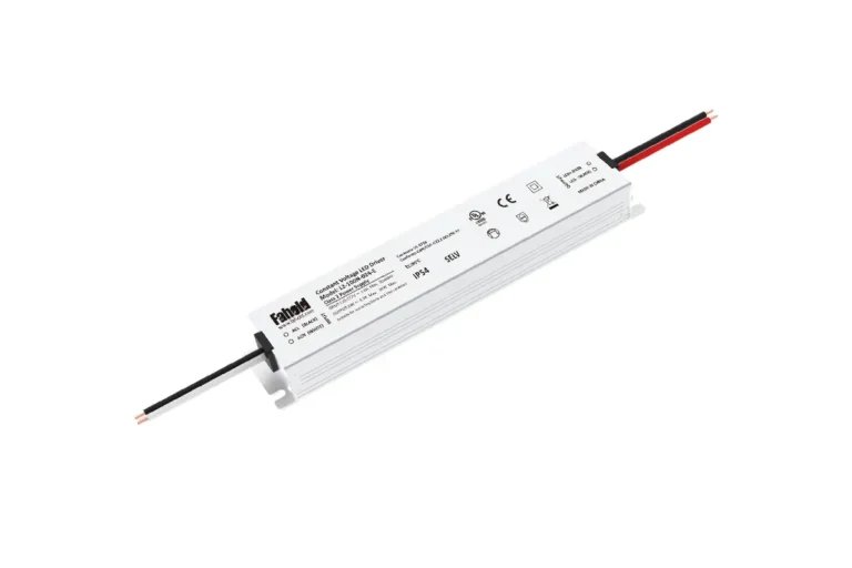
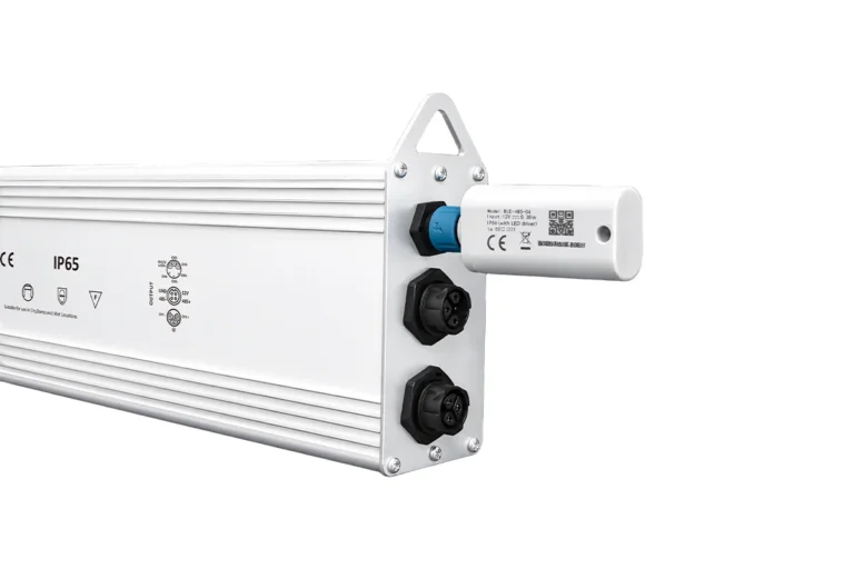
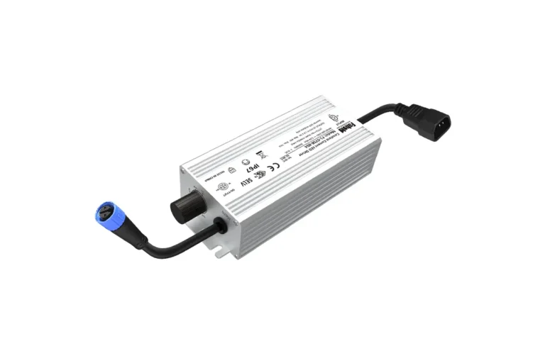
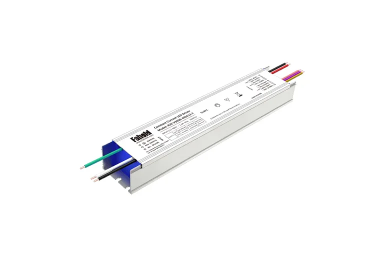
Once the electrical requirements are clear, the next step is to match the LED strip system with the appropriate power-supply architecture. FAHOLD offers several constant-voltage LED power supply platforms for different LED strip installation, wiring and control requirements.
Enclosed and Dimmable LED Strip Power Supply
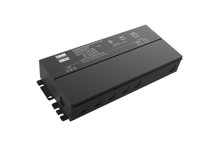
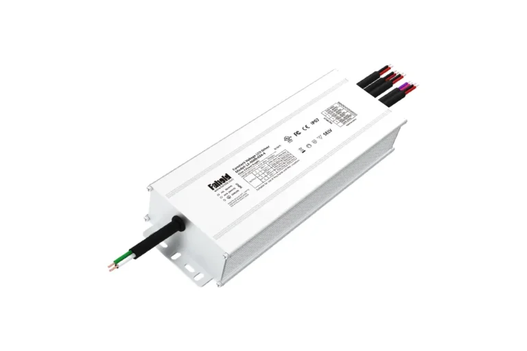
For architectural and commercial LED strip projects that require an enclosed Class 2 power supply, the FAHOLD L2-A Series is one of the most flexible options.
The platform provides 12V and 24V constant-voltage output with 100–277Vac input and covers power classes from 30W to 400W. Depending on configuration, it supports single- or multi-channel output together with TRIAC, ELV, MLV, 0–10V, PWM and potentiometer dimming.
This makes L2-A suitable for architectural linear lighting, commercial LED strip installations and projects where an integrated enclosure, Class 2 architecture and flexible dimming control are required.
Slim LED Strip Power Supply for Space-Constrained Installations
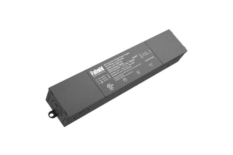
Where installation space is limited, the FAHOLD L2-E Series provides a slimmer single-output alternative.
L2-E models cover 12V and 24V constant-voltage systems from 20W to 150W with 120–277Vac input. The narrow enclosure format is particularly useful for LED strip lighting, cabinet lighting, signage and other installations where the power supply must fit into a restricted mounting space.
For example, the 24V range includes 60W, 100W and 150W configurations, allowing the power supply to be matched to different connected LED strip loads without moving to a larger multi-channel architecture.
Multi-Channel Power Supply for Multiple LED Strip Branches
Projects with several LED strip runs may benefit from a multi-channel power architecture rather than placing the entire load on one output. The FAHOLD L2 Series includes 12V and 24V constant-voltage models with multiple output channels for distributed LED loads.
The range includes configurations such as 12V 120W two-channel, 180W three-channel and 240W four-channel models, as well as 24V multi-channel platforms extending into higher total power classes.
A multi-channel supply does not eliminate the need to calculate each branch correctly, but it can simplify power distribution when several LED strip sections are supplied from one central power platform.
TRIAC / ELV / MLV Power Supply for North American LED Strip Projects
For North American installations using conventional phase-cut wall dimmers, the FAHOLD L2D Series provides another application-specific option.
L2D is a 100–120Vac Class 2 constant-voltage platform with 12V and 24V output. Type B configurations support TRIAC, ELV and MLV phase-cut dimming, making the series suitable for architectural and low-voltage LED strip projects where compatibility with common North American wall-dimming systems is required.
Match the Power Supply to the Project, Not Just the Wattage
These platforms are not interchangeable solely because their wattage ratings overlap. The final LED strip power supply should be selected from the actual strip voltage, connected load, output-current requirement, branch architecture, dimming method, AC input, installation environment and applicable certification requirements.
For broader application guidance, review FAHOLD’s LED strip lighting solutions. If the project requirements are already defined, send the strip voltage, W/m or W/ft, powered length, dimming method and installation conditions to FAHOLD for model matching.
20. Buyer / Engineer Specification Checklist
For a Commercial LED-strip project, prepare the following before requesting a power-supply recommendation:
| Parameter | Information to Provide |
|---|---|
| Target market | US / Canada / other |
| Application | Architectural / retail / signage / cabinet / OEM |
| AC input | Project requirement |
| Strip voltage | 12V / 24V / 48V / other |
| Strip power | W/m or W/ft |
| Total length | Total powered length |
| Length per feed | Electrical run per branch |
| Total maximum load | W |
| Output current | A |
| Branch count | Number of feeds/zones |
| Power-supply distance | Cable run |
| Dimming | None / PWM / 0–10V / DALI / phase-cut / other |
| Installation | Indoor / enclosed / outdoor |
| Environmental requirement | Project-specific |
| Certification | Project-specific |
| Mechanical limits | Maximum driver dimensions |
| Quantity | Sample / production requirement |
Providing these details makes it possible to evaluate the complete lighting system instead of recommending a product from wattage alone.
For FAHOLD’s LED-strip application context, continue to LED Strip Lighting.
If you already have a project specification, contact FAHOLD for product matching.
LED Strip Power Supply FAQ
What power supply do I need for LED strip lights?
Start with the LED strip’s rated voltage. For a conventional 24V constant-voltage strip, select a compatible 24V constant-voltage supply, then calculate total wattage/current and verify wiring, dimming, environmental, thermal and compliance requirements.
How do I calculate power-supply wattage for LED strips?
Multiply the strip’s rated watts per foot or meter by the total powered length. Then verify the candidate power supply’s usable output and derating rather than relying only on its nameplate wattage.
Is 12V or 24V better for LED strips?
Neither is universally better. Use the voltage the selected strip is designed for. At the same power, 24V draws less current than 12V, which can make longer distribution easier to manage.
Can multiple LED strips share one power supply?
Yes, when they require the same output voltage and the combined load, current, branch wiring, voltage drop and controls are within the system’s verified limits.
How far can a power supply be from an LED strip?
There is no fixed universal distance. It depends on current, conductor size, system voltage, cable length, allowable voltage drop and the strip’s feed/run requirements.
Does a bigger power supply fix dim LED strips at the far end?
Not necessarily. If the existing supply already maintains the correct source voltage, the problem may be conductor or strip voltage drop rather than insufficient wattage.
Do LED strips need a dimmable power supply?
It depends on the control architecture. Some systems use a downstream PWM controller with a compatible fixed-output supply, while others require a driver with an integrated dimming interface such as 0–10V, DALI or phase-cut.
Why do LED strips flicker?
Possible causes include overload, unstable connections, incompatible dimming/control, controller faults, supply/input issues or strip faults. Troubleshoot the complete system rather than assuming the power supply is always the cause.
Is every 24V LED strip system Class 2?
No. Nominal voltage alone does not establish Class 2 status. Verify the exact power unit, output limits, system configuration and applicable North American requirements.
Should I always leave 20% extra wattage?
No universal 20% rule applies to every installation. Calculate maximum load, check the manufacturer’s permitted loading and derating, then apply additional project margin where justified.
Need Help With Your LED Power Supply Project?
Tell us what you are working on. We will review your application and recommend the most relevant FAHOLD solution.