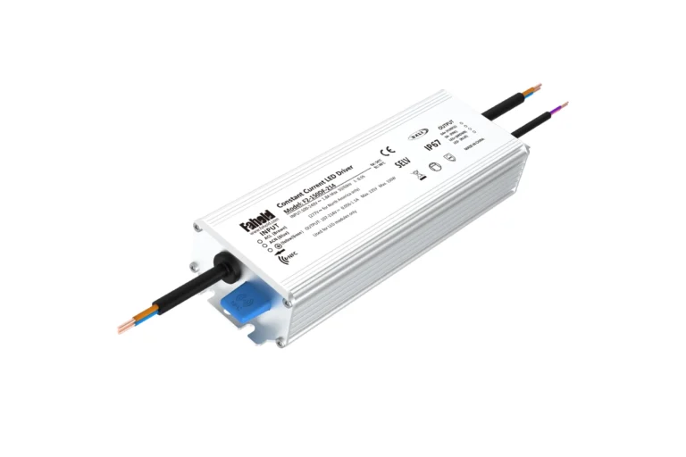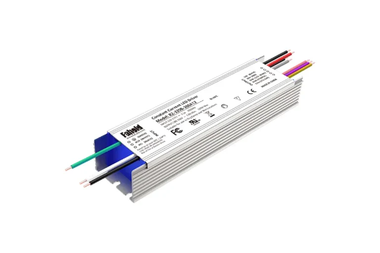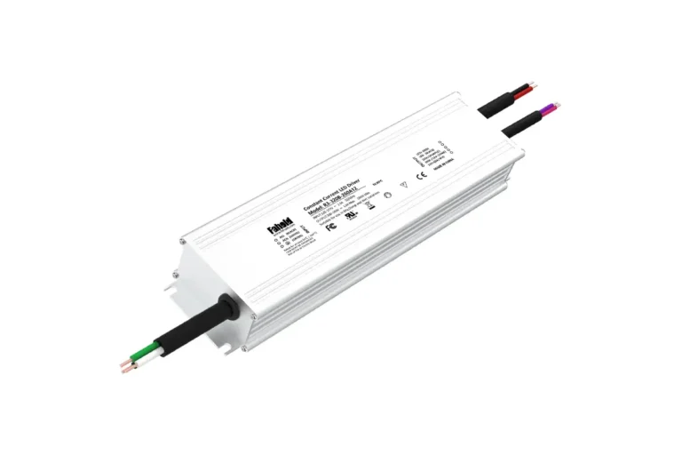
Table of Contents
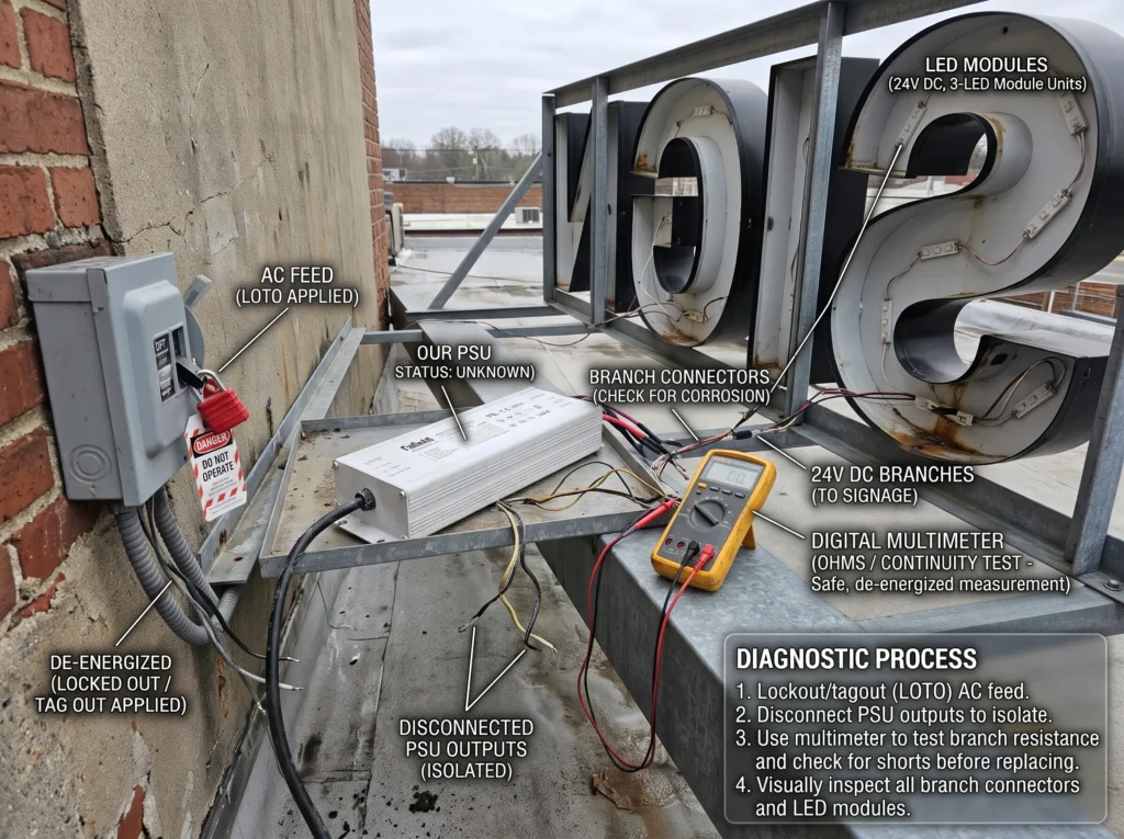
A sign that goes dark is not proof that its power supply has failed. A loose DC connection, an overloaded branch, a faulty LED module or water inside a cabinet can produce similar symptoms. Replacing the power supply without identifying the fault may leave the sign dark—or damage the new equipment.
An LED sign power supply replacement should start with two questions: What actually failed? and What must remain electrically, mechanically and operationally compatible? For an existing channel-letter sign or light box, matching the old driver’s voltage and advertised wattage is necessary in many cases, but seldom sufficient. Output architecture, load allocation, control equipment, wiring conditions and the sign’s compliance requirements can determine whether a proposed replacement works.
This guide walks sign shops, maintenance contractors and technical buyers through a practical replacement decision, from the first fault report to the information needed for a model recommendation. Installation, live electrical testing and changes to listed sign assemblies must be handled by appropriately qualified personnel under the applicable instructions and local requirements.
Before Ordering a New Driver, Confirm What Failed
An intermittent sign can be caused by a failing driver, but it can also be a healthy driver responding to a shorted or overloaded LED branch. The repair decision changes depending on which condition is present. A field technician should first document which letters are affected, whether the fault appears immediately or after warm-up, and whether the problem follows a particular output circuit.
| Observed symptom | Possible causes | What the technician should establish | Replacement decision |
|---|---|---|---|
| Entire sign remains off | AC supply interruption, disconnect, failed driver, control or timer fault | Is the expected input available to the system, and is the upstream control operating as intended? | Do not replace the driver until an upstream fault has been excluded. |
| One group of letters is dark | Failed output channel, loose termination, open circuit, faulty module section | Does the problem follow one documented DC branch rather than all branches? | Replace the driver only if the output itself is confirmed defective. |
| Sign blinks or cycles on and off | Overload, shorted branch, thermal protection, control fault or driver failure | Does the event correlate with total load, a particular branch, temperature or switching? | Correct the cause before fitting a new unit; an identical replacement can cycle too. |
| Letters near the end of a run look dim | Cable loss, poor connection, unequal branch loading, deteriorating modules | Is the voltage reaching the remote load consistent with the module requirements? | A larger driver may not solve excessive feeder resistance. |
| Fault appears after rain or cleaning | Moisture entry, damaged cable glands, corroded connections, unsuitable enclosure | Where did water enter, and what equipment has been affected? | Correct ingress and confirm environmental suitability before replacement. |
| Sign fails only when dimmed | Incorrect control interface, incompatible dimmer, minimum-load behavior | Is the dimming system compatible with the installed driver? | Select a compatible control architecture, not merely the same output voltage. |
A useful service report captures a photo of the original nameplate, the sign layout, the affected letters and the existing wiring diagram if available. When a driver fault is suspected, a qualified technician can use the manufacturer’s specified tests and appropriate instruments to distinguish output failure from an external load or wiring fault. Do not repeatedly energize an unidentified short circuit or attempt open-circuit measurements that the driver instructions do not permit.
Record the Original Power Supply and the Sign’s Actual Load
The old label is the starting point, not a complete replacement specification. It tells you what the unit was designed to deliver; it does not prove that all connected LED modules, wiring or controls are still in their original condition.
| Item to record | Why it matters for compatibility | Common mistake |
|---|---|---|
| Manufacturer and complete part number | Identifies the precise configuration and documentation | Treating a family name as a purchasable part number |
| Rated AC input and frequency | Must suit the building supply and control arrangement | Assuming a 120Vac-only unit can be used on a 277Vac circuit |
| Output type: constant voltage (CV) or constant current (CC) | Determines what kind of LED load the driver can operate | Replacing a CC driver with a 12V or 24V CV supply |
| Nominal DC output voltage | Must match the LED modules or strips | Substituting 24V for an existing 12V load |
| Rated output current and actual continuous power | Limits how much load each output can supply | Relying on the printed wattage class without checking volts × amps |
| Number of outputs and per-output rating | Defines the allowed circuit allocation | Treating two 5A outputs as one 10A output |
| Dimming and switching arrangement | Determines whether the original controls will work | Equating an on/off timer with a phase-cut dimmer |
| Environmental rating, dimensions and mounting | Affects safe fit and operating temperature | Assuming a waterproof label makes the entire sign waterproof |
| Listings, markings and sign-system requirements | Helps maintain the appropriate installation and certification scope | Assuming any individually certified driver is an approved substitution |
Where the original unit is no longer available, obtain the LED-module datasheet and reconstruct the connected load from the as-built sign. Count the modules or strip sections, record their rated voltage and maximum input power, and identify which branches receive power from which outputs. If those details cannot be confirmed, the replacement should remain a candidate—not an approved equivalent.
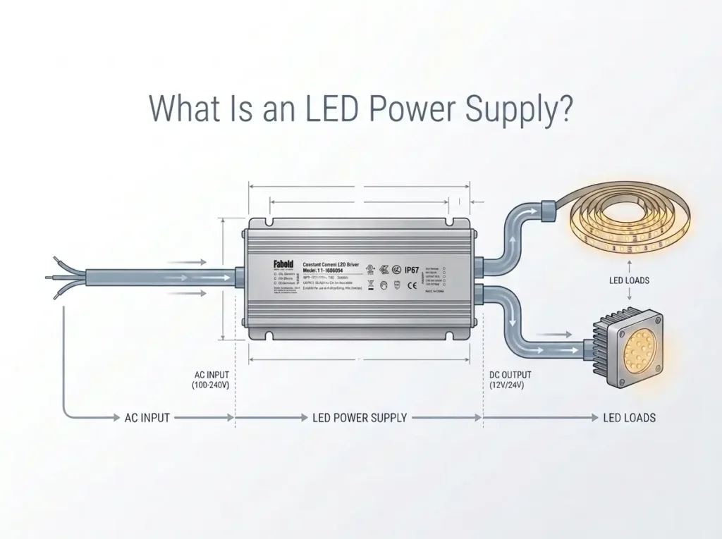
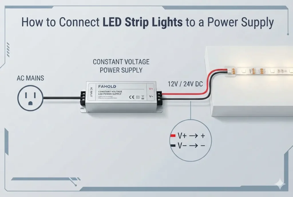
Constant voltage is not the same as constant current. Typical 12V or 24V channel-letter modules have their own current-limiting circuitry and use a constant-voltage supply. Other LED assemblies may need a controlled constant-current source. The printed output rating and module documentation decide which architecture applies; the word LED driver alone does not.
For a broader explanation of load types and input/output specifications, see the FAHOLD LED power supply selection guide. This replacement guide concentrates on decisions that arise after a sign has already been installed.
Five Compatibility Checks That Prevent a Bad Replacement
1. Match the LED Load’s Voltage, Not Just the Driver’s Power
A 12V LED module requires a properly regulated 12V supply; the same applies to a 24V module and an appropriate 24V supply. A proposed 24V/100W driver is not a substitute for a 12V/100W unit merely because the power rating matches. Applying the wrong voltage can produce inadequate operation or damage.
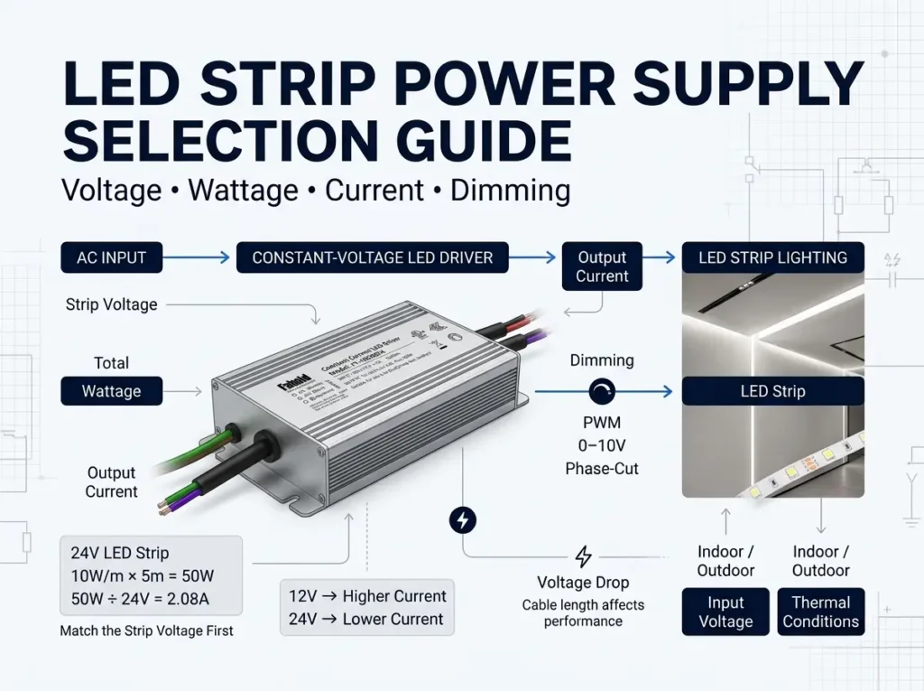
For a constant-voltage system, load current is estimated as watts ÷ volts. A sign drawing 96W at 12V draws approximately 8A in total; at 24V, the same 96W represents 4A. These figures describe different approved LED-load designs, not permission to change the voltage of the modules already installed.
A replacement may have a higher available wattage than the actual LED load without forcing extra current into a correctly designed constant-voltage load. That does not remove the need to verify minimum-load behavior where applicable, continuous ratings, thermal derating and each output’s current limit. Do not use a fixed 20% headroom rule as a substitute for the model’s instructions.
2. Preserve Output Topology and Branch Capacity
The number of output terminals does not by itself establish the number of independent, separately protected outputs. A multi-channel sign supply may place a current or power limit on each channel even when the overall nameplate shows a much larger combined wattage.
Consider a sign divided into two 12V branches, each drawing 48W (4A). A verified two-output supply rated at 12V/5A per output can serve those branches when all other requirements are met. But a redesign that puts both branches onto one 12V/5A output would demand 8A from a 5A channel. A 120W combined rating does not make that overload acceptable.
Likewise, do not tie regulated outputs together or parallel independent channels unless the manufacturer’s instructions expressly authorize the configuration. When replacing a single-output unit with a multi-channel unit—or the reverse—review the wiring plan, circuit segmentation and applicable listing conditions. It is a design change, not automatically a plug-in swap.
The existing 12V Class 2 guide for channel letters provides full per-channel sizing examples. For a replacement project, the immediate decision is whether the old circuit arrangement can be retained safely or must be redesigned.
3. Identify What the Controls Actually Do
A sign can have a timer, photocell, building-control relay, AC phase-cut dimmer, 0–10V signal or downstream PWM controller. These are not interchangeable functions.
| Existing control arrangement | What to verify when replacing the supply |
|---|---|
| Timer, photocell or relay that switches ordinary AC power on/off | Input rating, permitted switching behavior and startup performance; ordinary on/off control does not necessarily require a dimmable driver |
| TRIAC / ELV / MLV phase-cut dimmer | Whether the exact replacement model accepts that phase-cut input and is compatible with the specific dimmer |
| Separate 0–10V control wiring | Whether the driver has the appropriate control terminals, electrical interface and supported dim-to-off behavior |
| PWM control signal connected to the driver | Exact input specification, frequency range and compatible control implementation |
| Downstream DC PWM controller between supply and LEDs | Constant-voltage supply compatibility, switching load, controller current rating and the manufacturer-approved system architecture |
| No controls; fixed-output sign | A non-dimmable model may be appropriate if all other requirements match |
A 0–10V driver is not a direct substitute for a phase-cut driver just because both can dim. Similarly, a non-dimmable power supply should not be placed behind a phase-cut wall dimmer without explicit manufacturer approval. If the original controller is unidentified, record its part number before ordering a replacement.
The Signify Advance replacement guidance likewise identifies the original driver’s dimming interface, output type, current, voltage, Class 2 classification and physical size as information needed for proper matching.
4. Confirm Physical Fit, Input Conditions and Environmental Protection
A replacement that meets the electrical specifications may still be unsuitable for the sign cabinet. Check mounting orientation, enclosure clearance, wiring access, cable-entry method, connector type, thermal conditions and the actual AC supply. A slim driver can solve a space problem but cannot be selected solely from its dimensions.
Outdoor signs deserve particular care. A sign may be outdoors while its power supply sits in a protected compartment; another installation may expose the supply directly to rain or washdown. The environmental rating must suit the actual driver location, and cable entries, junction boxes, splices and drainage remain part of the complete installation. IP67 marking on one product does not certify the finished sign assembly or guarantee resistance to pressure washing.
For installations where exposure is the dominant design concern, use FAHOLD’s separate outdoor signage IP67 selection guide rather than treating this replacement checklist as a full waterproofing design manual.
5. Check the Sign-System Approval, Not Only the Driver Label
North American electric signs are subject to sign-system and installation requirements that cannot be resolved solely by buying a power supply with a familiar safety mark. UL Solutions identifies UL 48, UL 879, UL 879A and NEC Article 600 among common electric-sign and sign-component requirements.
Replacing a failed component in an existing sign is not necessarily the same compliance exercise as converting an older sign to LED technology or changing the sign’s electrical architecture. The sign manufacturer, qualified installer or authority having jurisdiction may need to evaluate substitutions or field modifications against the assembly’s instructions and certification conditions. UL’s sign-retrofit guidance explains why the approved kit and the scope of modifications matter. Do not describe an individual component’s listing as proof that every sign conversion or replacement is automatically approved.
Two Replacement Scenarios: One Simple, One Requiring a Redesign
The following scenarios are illustrative engineering examples, not FAHOLD field-test results or automatic replacement approvals.
Example A: A 12V Channel-Letter Sign With an Apparently Failed 60W Supply
A storefront sign has 40 LED modules rated at 12V and 1.2W each. The original power supply is marked 12V/5A (60W), single output. The sign does not illuminate. Inspection of the original label alone is not enough to conclude that the driver failed: the technician must still establish that input power, the DC branch, module condition and controls are not causing the symptom.
If the driver is confirmed defective and the sign load is intact, the documented design load is 40 × 1.2W = 48W, or 4A at 12V. The original 60W/5A rating leaves 12W/1A of nameplate capacity under the stated assumptions. That calculation is not an endorsement of 80% loading for every product; the replacement’s continuous rating and installation derating govern.
A candidate replacement must provide 12V CV output, sufficient permitted current, the correct AC input range, suitable physical and environmental characteristics, and the approval evidence required for this particular sign. The installer must also check whether a dimmer is present. A model marked 12V/60W but intended for a different control architecture may fail despite its matching voltage and wattage.
Decision: If the diagnosis confirms a failed driver and the original architecture remains appropriate, a same-voltage, same-output-type replacement with verified current capacity may be reasonable. Do not change LED modules or branch wiring merely to accommodate an arbitrarily selected supply.
Example B: A 24V Cabinet Sign Moving From One Output to Distributed Circuits
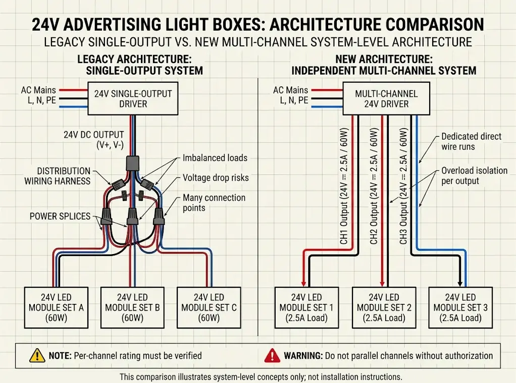
A large cabinet sign has three LED sections, each rated at 24V/60W. The total design load is 180W, corresponding to 7.5A at 24V. The original arrangement uses one output and a distribution harness. A proposed replacement uses three separate outputs.
The new architecture could be suitable only if each proposed channel is rated for at least the actual connected current under the required operating conditions, the supply’s combined rating is adequate, and the sign can be rewired in accordance with the manufacturer’s instructions and its compliance requirements. Each 60W section draws 2.5A at 24V. A channel rated for 2A would be inadequate even if the unit’s total advertised wattage were higher than 180W.
The old harness cannot automatically be reconnected without change. The technician must identify branch endpoints, polarity, conductor capacity and allowable output arrangements. If long feeders caused brightness variation before the failure, moving to more outputs does not automatically eliminate voltage drop; load-side voltage still needs verification under operating conditions.
Decision: This is a controlled electrical redesign, not a direct part-number substitution. Do not approve the replacement from total wattage alone. For larger signs, compare the actual channel requirements with the available FAHOLD L2 multi-channel power supply platform and request model-level specifications before changing the circuit layout.
What a Replacement Power Supply Cannot Fix: Voltage Drop and Bad Connections
Signage power supply replacement requests often begin with a complaint about uneven brightness rather than a confirmed failed driver. A remote channel letter may look dim because the supply is undersized, but it can also look dim because a long feed or poor termination is consuming too much voltage before it reaches the LED modules.
Consider a hypothetical 12V sign branch drawing 4A. If the supply terminals are at a regulated 12.0V while the far LED branch receives only 10.9V under load, the difference is 1.1V—approximately 9.2% of the nominal 12V. That is a distribution problem worth investigating. The actual permitted module voltage range and installation test method determine whether the operating point is acceptable. Replacing a correctly functioning 12V driver with a larger-wattage 12V driver does not inherently remove resistance from the wiring.
For a verified voltage-drop problem, the corrective design may involve shorter branch feeds, suitable conductor sizing, improved terminations, appropriate distribution, or relocating the power supply. Changes should follow module instructions, wiring requirements and the sign’s approval conditions. A qualified technician should perform any energized measurement; the article is not a live-wiring procedure.
A second useful distinction is thermal shutdown versus load fault. If a sign illuminates normally at first and stops after warm-up, the technician should document cabinet temperature, airflow, load, mounting and the behavior of the affected circuits. Thermal protection in a functioning unit may be a symptom of an unsuitable installation, while repeating the fault with a new unit can shorten service life and delay the real repair.
Which FAHOLD Sign Power Supply Family Should Be Evaluated?
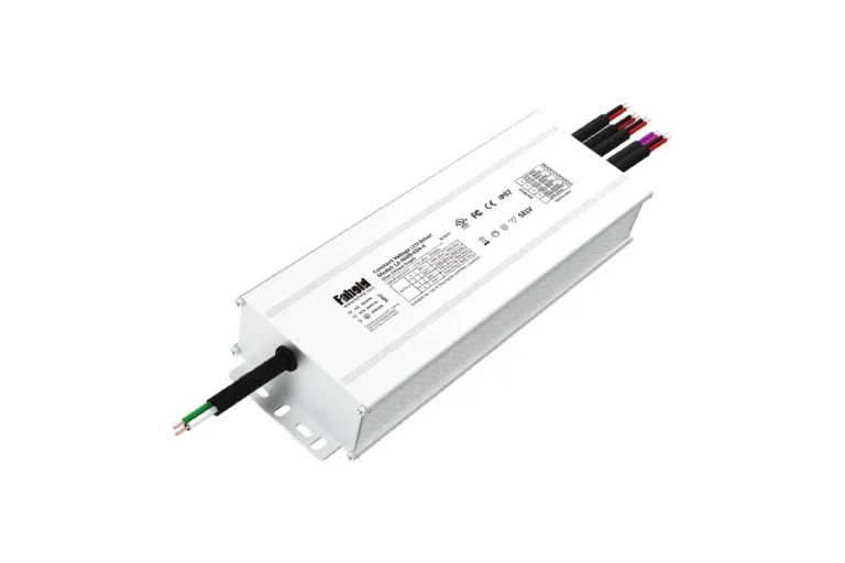
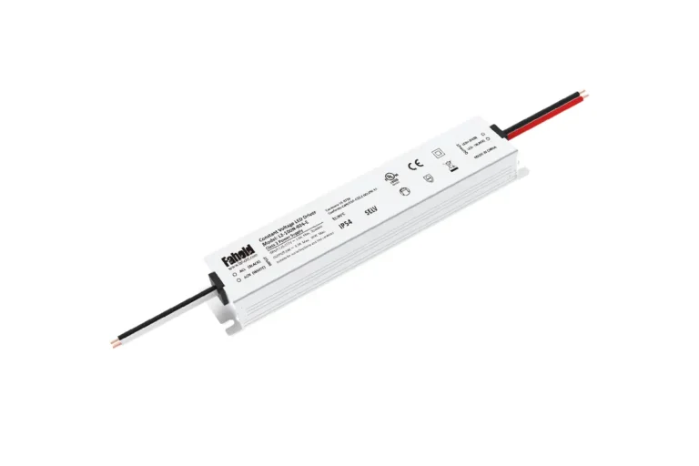
FAHOLD’s LED sign power supply range organizes constant-voltage products for channel letters, illuminated signs, light boxes and other commercial signage by output structure and installation requirements. The families below are screening candidates, not a manufacturer-certified interchangeability list between old and new part numbers.
| Replacement situation | Candidate FAHOLD platform | Confirm before specifying |
|---|---|---|
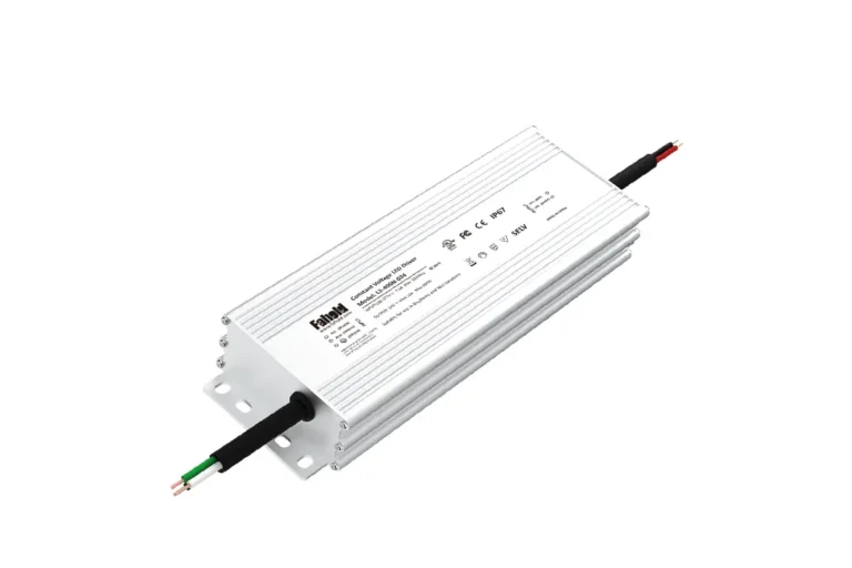
| Compact 12V or 24V fixed-output channel letters with limited installation space | L2-E slim single-output | Exact rated input, actual volts/amps, cabinet fit, non-dimmable operation, IP option and required compliance documentation |
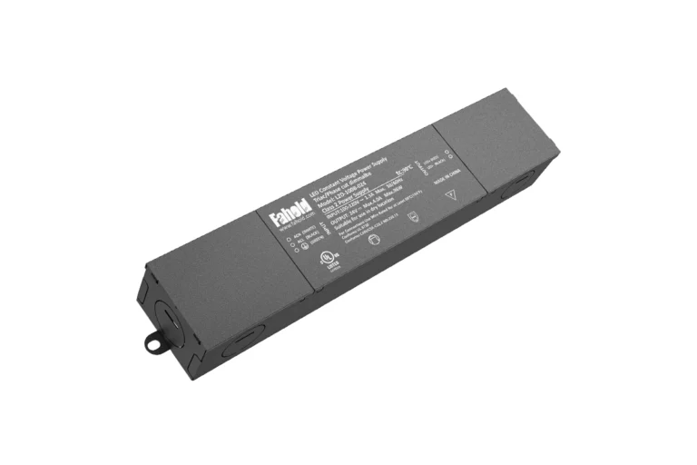
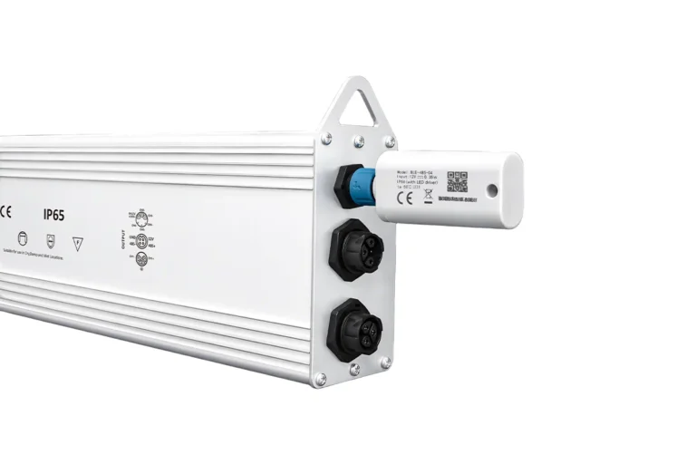
| Existing sign with two or more independently designed DC branches | L2 multi-channel Class 2 | Number of channels, each channel’s rating, total output capacity, Class 2 documentation and approved wiring configuration |
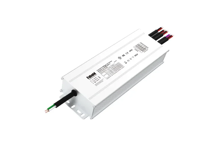
| Larger fixed-output sign requiring an isolated single-output supply | L3 high-power isolated | Matching 12V/24V/36V/48V LED load, rated current, input platform, environmental rating and non-dimmable suitability |
| Sign requiring a specific dimming interface or special enclosure | Model-specific evaluation outside the standard fixed-output shortlist | Control method, exact configuration, input voltage, output limits and approvals; do not assume every L2-series or L2-E/L3 model supports dimming |
The L2-E and L3 families are presented as non-dimmable platforms in FAHOLD’s current product information. The L2 family includes distinct output configurations; consult the precise SKU rather than inferring a channel rating from the family name. Signage requiring approved phase-cut, 0–10V or PWM dimming should be routed to the relevant configured dimmable platform only after the control system has been identified and model compatibility confirmed.
If the original sign used a single output, the single-output LED sign power supply category is a useful starting point. If it used separate Class 2 output circuits, verify the intended branch topology against the documented L2 model table first.
The fastest route to a reliable recommendation is to send the old label and a simple sign wiring sketch alongside the new model requirements. The purpose of the product category is to narrow purchasable options; the purpose of this guide is to prevent incorrect substitutions.
Commissioning Checklist: Confirm That the Replacement Actually Works
A successful replacement is not simply a sign that turns on once. The qualified installer should document whether the driver remains within the prescribed operating limits and whether the complete sign functions under its normal controls and environment.
| Acceptance point | Verification and evidence | Pass criteria / disposition |
|---|---|---|
| Model identity | Photograph exact replacement part number and installed location | Matches approved submittal, configuration and documentation |
| AC input and isolation | Follow manufacturer and site procedures; confirm the correct supply and protective measures | Input and protection meet the approved design |
| Output type and nominal voltage | Compare datasheet with the LED modules and approved test results | Correct CV/CC type and rated output for the connected load |
| Branch load | Check the load schedule and model’s individual channel ratings | Every branch and the combined load remain within permitted limits |
| Sign behavior | Observe every letter or LED section at intended operating states | No unexpected dark sections, cycling or abnormal brightness differences |
| Controls | Check the existing timer, sensor or supported dimming settings | Normal switching and compatible dimming behavior across required settings |
| Distribution | Assess branch voltage drop, connectors and wire routing under the manufacturer’s procedures | Load-end operation stays within LED-module requirements |
| Environment | Inspect enclosure, cable entries, mounting, airflow and water management | Installation meets specified location and temperature conditions |
| Documentation | Preserve the old label, new datasheet, photos and any required sign-system records | Sign owner receives traceable replacement and service records |
What to Send When Requesting a Replacement Power Supply for LED Signs
A supplier cannot reliably quote an equivalent from the phrase “24V 150W sign driver” alone. For a signage power supply replacement, the inquiry should contain enough information to check electrical compatibility, physical fit and any required approval conditions.
| RFQ information | Example of useful detail |
|---|---|
| Existing unit | Original manufacturer, full model number, clear nameplate photo and reason for replacement |
| LED modules | Manufacturer/part number, CV or CC requirement, rated voltage, quantity and watts per module |
| Connected load | Calculated maximum watts/amps, including the load assigned to each output |
| AC supply | Measured/design system voltage, frequency and existing control arrangement (verified by qualified personnel) |
| Output layout | Single output or multiple independent outputs, wiring sketch, approximate DC feeder distances |
| Control method | Fixed-output, timer, photocell, phase-cut, 0–10V, PWM or other identified arrangement |
| Installation | Sign type, cabinet clearance, ambient conditions and dry/damp/wet exposure |
| Compliance | Country/market, applicable sign listing, component certification and retrofit/field-modification considerations |
| Procurement | Quantity, intended project timing, samples and any required drawing or datasheet review |
This information is especially helpful for a channel letter power supply replacement, because different letters can contain unequal LED loads and the wiring may distribute current across separate circuits. A photograph of the sign face cannot substitute for a branch-load schedule.
Need to replace an existing unit? Compare FAHOLD’s signage power supply models by voltage and output arrangement, then send the original nameplate, connected load and installation details to FAHOLD for a model-specific recommendation and quotation. A proposed alternative should be reviewed against the latest datasheet and the sign’s actual requirements before approval.
Frequently Asked Questions
Can I replace a 12V LED sign power supply with a higher-wattage model?
Often a higher-capacity constant-voltage supply can operate a compatible 12V load, provided the exact output voltage, current behavior, control architecture, minimum-load requirements where applicable, installation conditions and approvals all match. Higher wattage does not fix a wrong voltage, damaged feeder or incompatible dimmer. Verify model-level continuous ratings and derating.
Can I use a 24V power supply to replace a 12V channel-letter driver?
No—not while retaining LED modules rated for 12V. The supply voltage must match the connected LED load. Converting a sign from 12V to 24V is a separate system redesign involving different approved modules and wiring, not a direct driver replacement.
Can I replace a dual-output sign power supply with a single-output model?
Only after a qualified review of the circuit layout, combined and branch currents, wiring, protection and sign-system requirements. Two 12V/5A outputs are not automatically equivalent to one 12V/10A output. Never combine separate regulated outputs without explicit manufacturer approval.
Why are some letters still dim after changing the power supply?
The cause may be voltage drop, a weak connection, a damaged LED module or uneven branch loading. Compare the actual load-side conditions with the module maker’s requirements rather than assuming a more powerful driver will correct distribution losses.
Does a new IP67 power supply make an outdoor sign waterproof?
No. The complete sign still depends on cable entries, splices, junction boxes, enclosure design, drainage, installation and the product’s specific location rating. IP67 does not by itself prove that a product is approved for every wet-location or cleaning condition.
Does a UL-listed driver guarantee that the repaired sign keeps its certification?
Not by itself. The applicable sign assembly, component certification, replacement instructions and any field modification or retrofit requirements still matter. Review the sign’s listing conditions and requirements imposed by the authority having jurisdiction where necessary.
Is an exact model-number match always required?
An identical approved replacement is often the simplest path, but an alternative may be possible when its electrical ratings, output architecture, controls, environment, dimensions and sign-system requirements have been reviewed and accepted. A series name or matching wattage is not evidence of automatic interchangeability.
What if the old power supply label is unreadable?
Document the sign model, LED-module part numbers, branch diagram, input and control equipment, and installation environment. Obtain original manufacturer documentation when possible. If the connected load cannot be established safely, do not order a supposed equivalent based on visual size or guesswork.
Need Help With Your LED Power Supply Project?
Tell us what you are working on. We will review your application and recommend the most relevant FAHOLD solution.