Table of Contents
An IP67 label does not, by itself, make a power supply suitable for every outdoor sign. A unit can meet its enclosure rating and still be the wrong choice if its output voltage does not match the LED modules, its available power falls under thermal derating, or water can enter through field wiring and connectors.
For a reliable selection, start with the LED load and installation details. Then verify the power supply’s IP configuration, output capacity, operating-temperature limits, wiring arrangement and certification for the intended market. The model number matters: protection ratings, output options and approvals can vary within the same product series.
Quick Selection Check
| Selection area | What must match or be verified | Evidence to keep |
|---|---|---|
| Output system | Required DC voltage, constant-voltage or constant-current architecture, and load current | LED module datasheet and driver datasheet |
| Water and dust exposure | Whether the installation needs IP67 and whether the rating applies to the exact model | Model-specific datasheet and installation instructions |
| Power capacity | Total connected load, design allowance and temperature derating | Load calculation and derating curve |
| Wiring | Cable length, wire gauge, branch current, connectors and field splices | Wiring layout and voltage-drop calculation |
| Installation conditions | Enclosure space, ventilation, ambient temperature, drainage and corrosion exposure | Sign construction details and installation plan |
| North American requirements | Applicable listing, Class 2 status where required, and project-specific conditions | Current certification records and approval documents |
Treat this as a screening checklist, not proof of compatibility. Final selection depends on the exact driver, LED load and installed configuration.
1. Decide Whether IP67 Fits the Installation
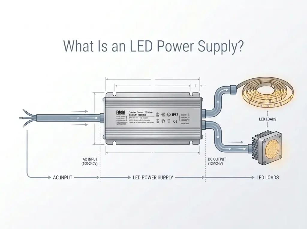
IP67 is an enclosure ingress-protection classification associated with IEC 60529. The first digit, 6, indicates dust-tight protection under the specified test. The second digit, 7, relates to protection against the effects of temporary immersion under defined test conditions. It does not mean that the product can withstand every type of water exposure.
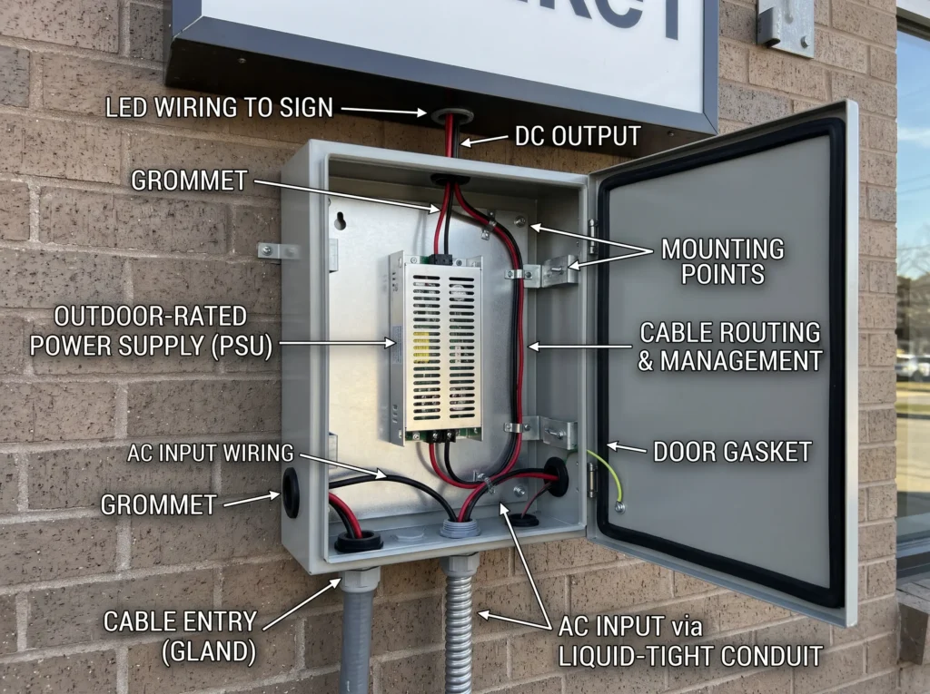
For outdoor signage, the key question is not simply whether the sign is outside. It is how the power supply is mounted and what can reach it during normal use, maintenance and severe weather.
Match the rating to the actual water exposure
| Installation condition | What to check before selecting the supply |
|---|---|
| Wall-mounted sign exposed to rain | Confirm wet-location suitability and the protection rating of the exact driver model |
| Sign cleaned with a hose or pressure washer | Verify actual water pressure, spray direction and cleaning procedure; IP67 alone does not establish suitability for high-pressure water jets |
| Power supply installed at the bottom of a sign cabinet | Check whether water can collect around the unit, terminals or cable entries; provide drainage and mounting clearance as required |
| Large day-to-night temperature swings | Assess condensation risk inside the sign and around wiring connections |
| Coastal or corrosive environment | Check enclosure materials, fasteners, connectors and any specified corrosion resistance separately |
| Power supply inside a sealed sign body | Confirm thermal design as well as ingress protection; a sealed space can retain heat |
A power supply’s rating applies to the tested product configuration. It should not be assumed to cover a separately installed junction box, field splice, connector or cable entry unless the product documentation and assembled installation support that conclusion.
Check the complete wiring path
Inspect where AC enters the enclosure, where DC output cables leave it, and where LED branches connect. A correctly rated power supply can be undermined by a poorly sealed cable gland, an unsuitable connector or a field splice exposed to moisture. Follow the manufacturer’s instructions for cable entry, mounting orientation, strain relief and sealing.
Do not add sealant or modify the enclosure unless the manufacturer permits it. Unapproved modifications can affect heat dissipation, serviceability and the validity of the product’s protection claims.
2. Match the Output Voltage and LED Load Type
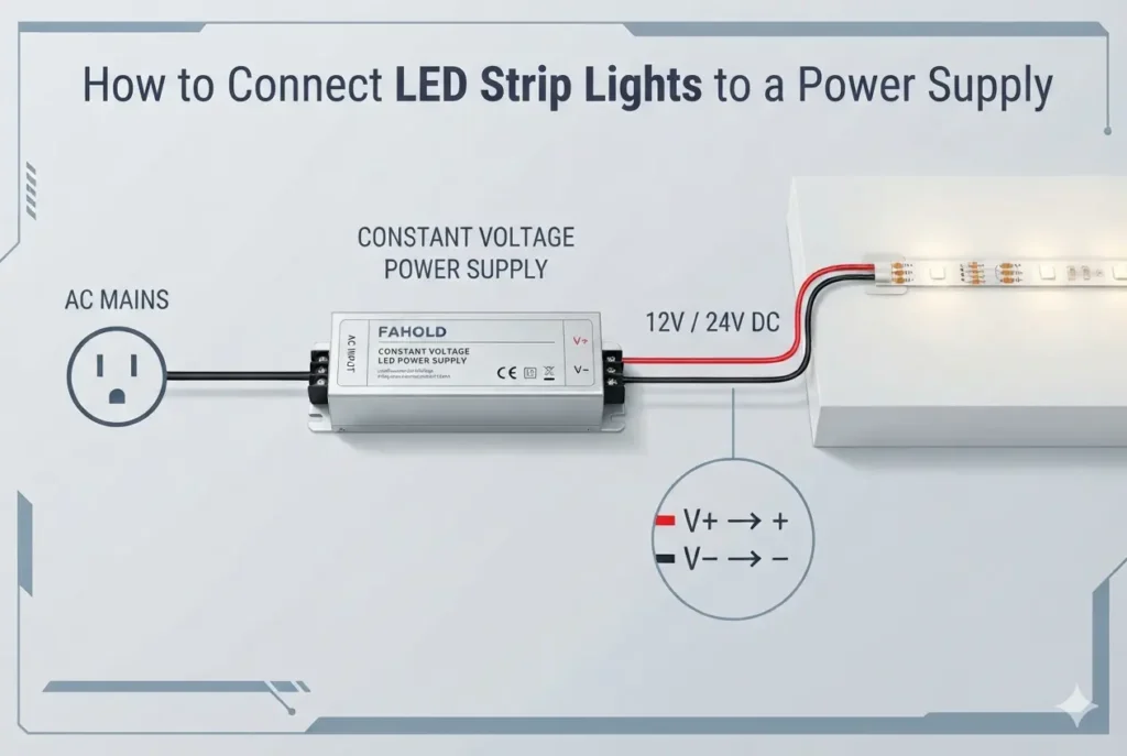
Confirm the LED module or strip specification before comparing wattage. Most low-voltage signage modules are designed for a particular DC voltage, commonly 12V or 24V, and a constant-voltage supply must match that requirement. A constant-current LED load needs a driver designed for its specified current and voltage range; a constant-voltage supply is not a substitute.
Choose 12V or 24V from the LED specification
Do not change a 12V sign to 24V simply because a 24V supply is available at the required wattage. The LED modules must be rated for the selected voltage. If the sign design permits either system, compare current, cable length, module arrangement and the manufacturer’s wiring recommendations.
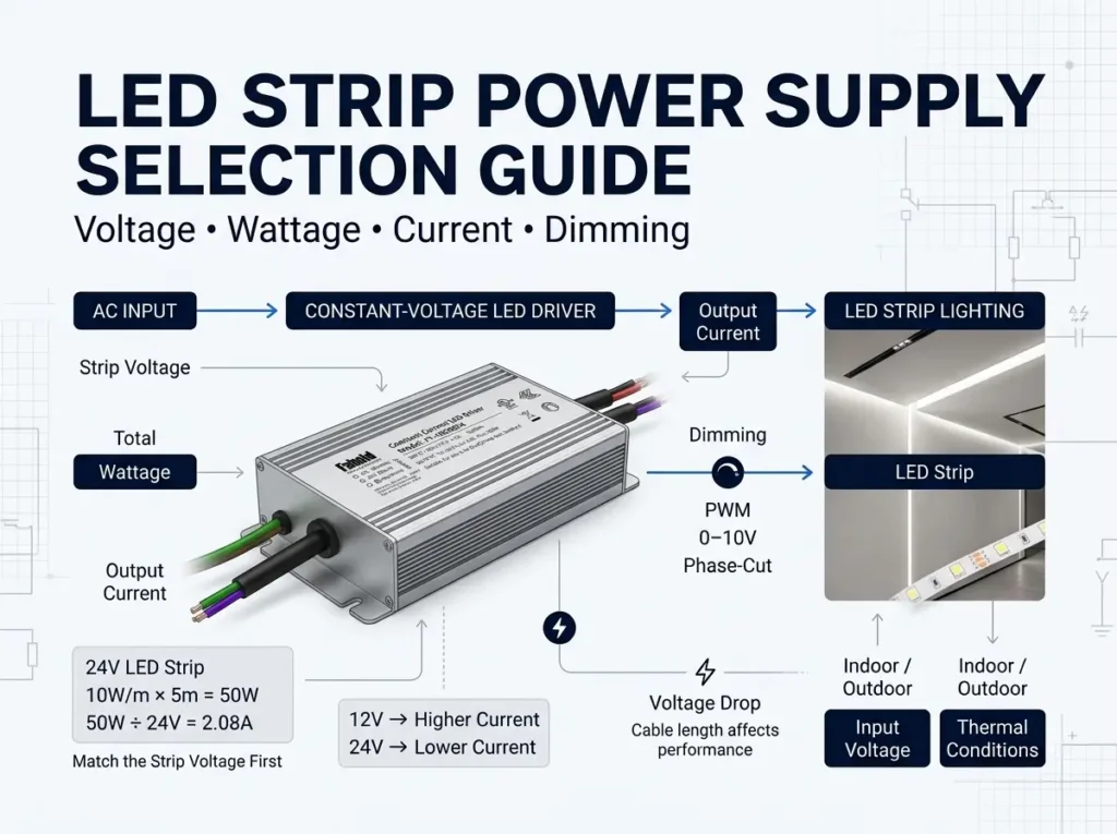
For the same power, a 24V system draws half the current of a 12V system. For example, a 120W load draws approximately 10A at 12V or 5A at 24V, before considering operating tolerances. Lower current can reduce cable losses for a given conductor resistance, but it does not remove the need to calculate voltage drop or confirm the LED module’s permitted input range.
Also verify the AC input range against the building supply. A product marked for 100–277Vac should not be assumed suitable for every site condition without checking its rated operating range and installation instructions.
Confirm control requirements before ordering
If the sign uses fixed-output LED modules, a non-dimmable supply may be appropriate. If the project needs dimming, color control or separate lighting zones, confirm the control method and wiring architecture. A dimming feature listed for one model does not mean every model in the family supports it.
3. Calculate Power Capacity and Check Thermal Derating
The connected LED load is the starting point for wattage selection. The power supply’s usable output under actual installation conditions determines whether that selection remains valid.
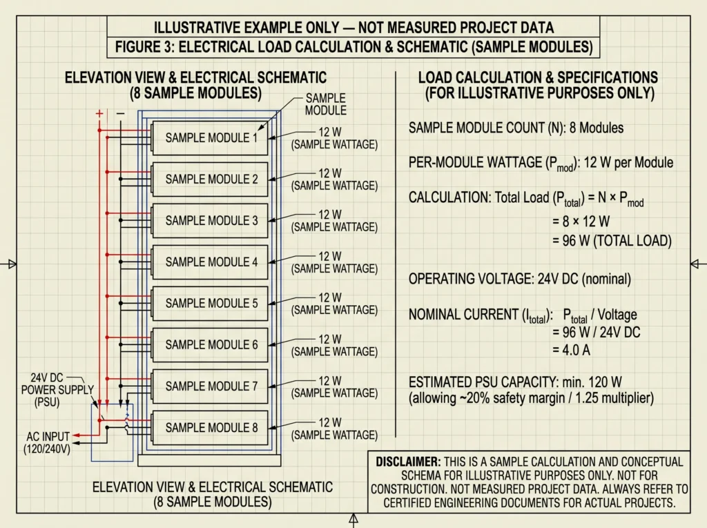
Consider a sign built with 80 LED modules, each rated at 1.5W:
Total connected load = 80 modules × 1.5 W per module = 120 W
If the project design specifies that the normal connected load should not exceed 80% of the power supply’s rated capacity, the initial capacity target is:
Required rated capacity = 120 W ÷ 0.80 = 150 W
The 80% figure is an example design criterion, not a universal requirement for all LED power supplies. The final selection must follow the specific driver’s datasheet, derating curve and project requirements. A nominal 150W unit is not automatically sufficient if the manufacturer limits output at the expected ambient temperature or in the intended mounting arrangement.
Evaluate the temperature inside the sign
Outdoor ambient temperature is only part of the thermal picture. A power supply mounted inside a dark, enclosed cabinet can operate at a higher temperature than the surrounding air. Sun exposure, nearby electronics, limited airflow and the distance between the supply and the sign’s rear panel can all affect internal temperature.
Check the manufacturer’s temperature-versus-load curve and any restrictions on mounting orientation, clearance or enclosure use. If the documentation requires output derating above a stated temperature, apply that reduction to the available capacity before approving the model.
| Power check | Why it matters | Common selection error |
|---|---|---|
| Total LED load | Establishes the required continuous output | Counting modules but missing additional branches |
| Rated output capacity | Sets the model’s nominal maximum output under specified conditions | Selecting a supply whose rating exactly matches the calculated load without checking project criteria |
| Temperature derating | Shows how much output is available at the expected operating temperature | Using a room-temperature rating for a hot, enclosed sign |
| Output current and channel limits | Confirms that each output or branch stays within its limit | Checking total wattage but overlooking per-channel current |
| Installation clearance | Affects heat transfer and service access | Installing the supply tightly against insulation or other heat-producing equipment without checking instructions |
Do not assume that a higher-wattage supply is always the better choice. It still needs the correct output voltage, wiring arrangement, environmental rating and any required safety approvals. Excess capacity does not correct a mismatch elsewhere in the system.
4. Account for Voltage Drop on Long Sign Runs
Voltage drop is especially relevant when the power supply is located far from the illuminated letters or when a sign has many distributed branches. The supply may measure correctly at its output terminals while the voltage at the farthest LED module is lower.
Start with the actual cable route, conductor size and current on each branch. Calculate the expected voltage drop using the cable manufacturer’s resistance data or an appropriate engineering method, then check the result against the LED module’s permitted input range. Where practical, measure voltage at both the driver and the farthest load during a representative operating condition.
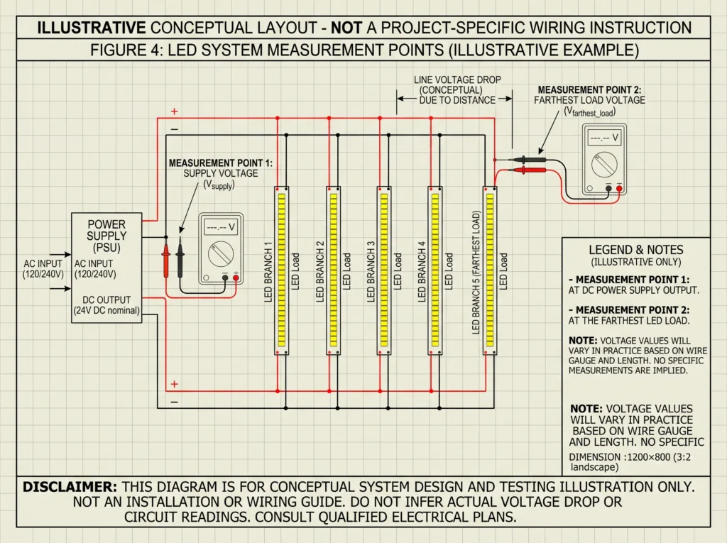
| Observed symptom | Possible cause | First checks |
|---|---|---|
| Letters near the supply are brighter than those farther away | Voltage drop along the power cable or LED run | Voltage at the farthest module, wire gauge, cable length and branch current |
| Some letters are dimmer than others | Unequal branch loading, connection resistance or different cable lengths | Branch layout, connector condition and load distribution |
| Brightness falls when all modules are on | Supply capacity, thermal derating or wiring losses | Output current, temperature conditions and voltage at the load |
| One section flickers or cuts out intermittently | Loose or moisture-affected connection, damaged cable or a local load issue | Field splices, connector sealing and branch wiring |
Avoid compensating for a long run by raising the supply voltage unless the selected product is designed for adjustment and the LED manufacturer permits it. Overvoltage at the nearest modules can create a new problem while the far end still receives insufficient voltage. Depending on the layout, a better solution may be a larger conductor, shorter branch runs, a revised distribution point or multiple appropriately rated supplies.
5. Select the Power Supply Architecture for the Sign
The sign’s physical layout can be as important as its total wattage. A narrow channel letter, a shallow cabinet and a large multi-section sign place different demands on enclosure size, cable routing and output distribution.
| Power supply architecture | When to consider it | What to verify |
|---|---|---|
| Slim, single-output supply | Narrow channel letters or limited mounting depth | Exact dimensions, output voltage, wattage, IP configuration and installation clearance |
| Multi-channel supply | Loads need to be split across multiple branches | Number of outputs, per-channel current, total capacity and the exact wiring diagram |
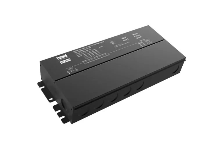
| Higher-power single-output supply | Larger fixed-output loads or centralized DC distribution | Total output current, cable sizing, distribution layout, heat and service access |
| Dimmable supply | Sign lighting requires a supported dimming function | Exact control method, compatible controller and model-specific wiring |
| Non-dimmable supply | The sign runs at a fixed output level | Confirm that no dimming or control function is required by the project |
A multi-channel unit can simplify branch distribution, but the total rated wattage does not override individual channel limits. Likewise, a slim supply may fit the available space yet still be unsuitable if the enclosure cannot dissipate heat or the cable entry is difficult to protect.
6. Verify North American Safety and Project Requirements
IP rating and electrical safety approval answer different questions. IP67 describes ingress protection under defined test conditions; it does not establish that the product meets every electrical safety requirement for a particular sign installation.
For U.S. electric-sign projects, UL 48 is the standard covering electric signs, including LED-illuminated signs. UL Solutions also identifies UL 879 and UL 879A as relevant standards for sign components and LED sign or retrofit kits. Which requirements apply depends on the product, sign construction, installation and approval route. See UL Solutions’ electric sign and sign component certification overview and the UL 48 standard page.
Before ordering, ask the supplier for documentation that identifies the exact model and configuration. Check the listing or certification record rather than relying only on a logo in a catalogue. If Class 2 output is required by the sign design or applicable code, confirm the status and limits of the exact model; do not infer Class 2 compliance from low output voltage or wattage alone.
The sign manufacturer or project’s responsible electrical professional should confirm the requirements that apply to the finished sign and installation. A power supply certificate does not automatically certify the complete sign assembly.
7. Which FAHOLD Series Is Worth Evaluating?
FAHOLD’s L2-E, L2-F and L3 families provide different constant-voltage options, but they should be treated as candidate platforms rather than interchangeable products. The exact model, IP configuration, output, control method and certification record need to match the project.
| FAHOLD series | Published platform overview | Check before selecting |
|---|---|---|
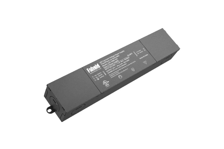
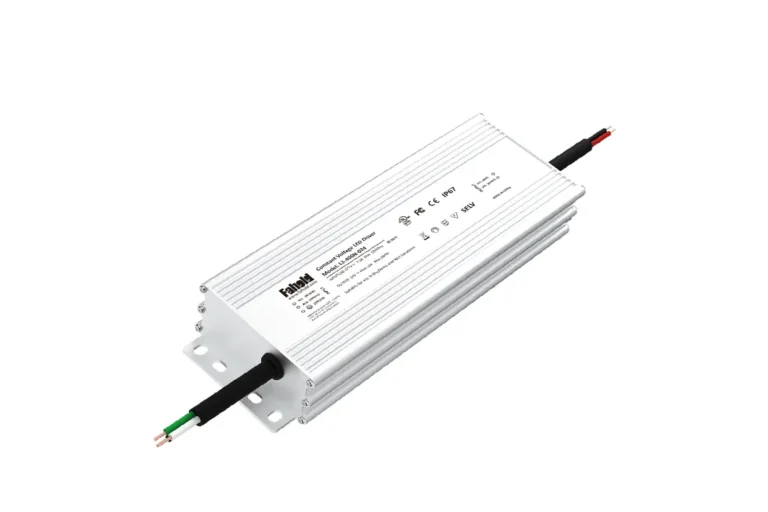
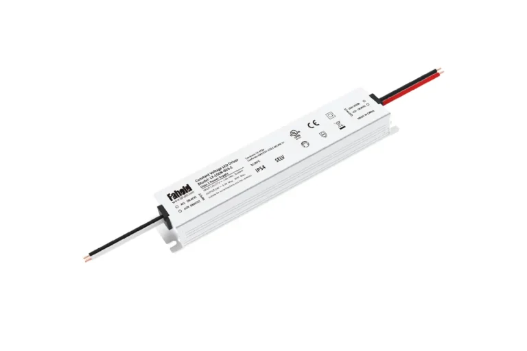
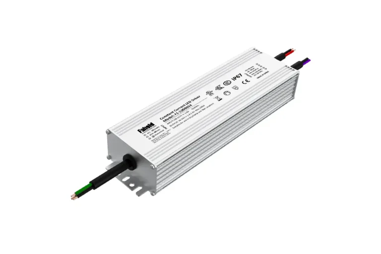
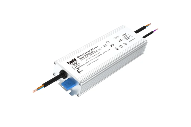
| L2-E Slim LED Sign Power Supply | 20–150W, 12V/24V constant-voltage, single output, non-dimmable; IP65/IP67 options by model | Confirm exact IP rating, input range, dimensions, Class 2 status where relevant and current certification documentation |
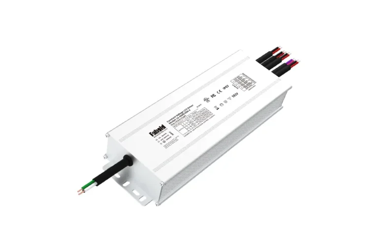
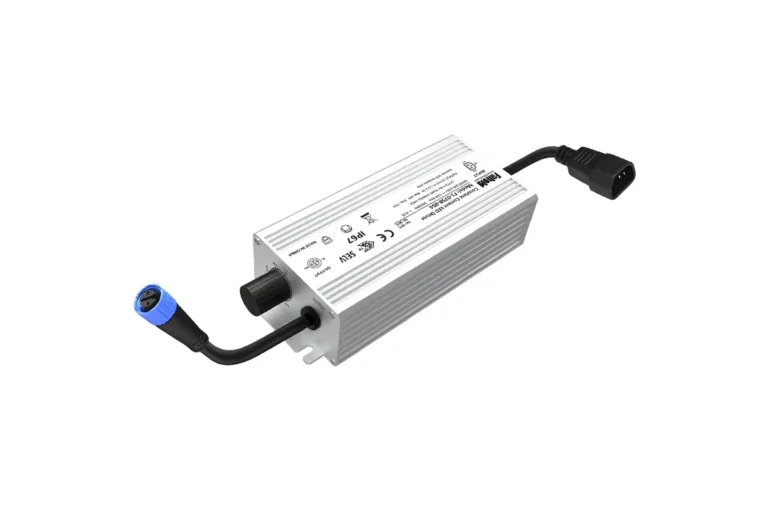
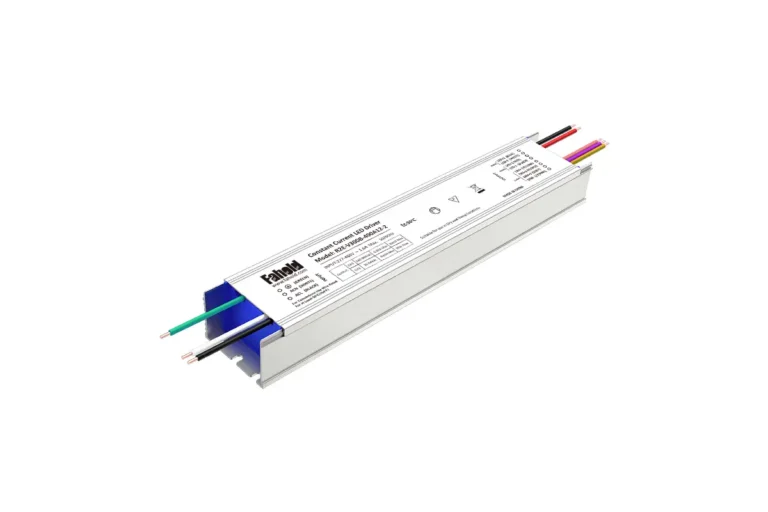
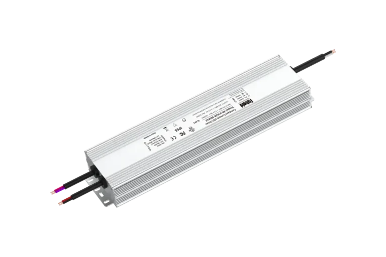
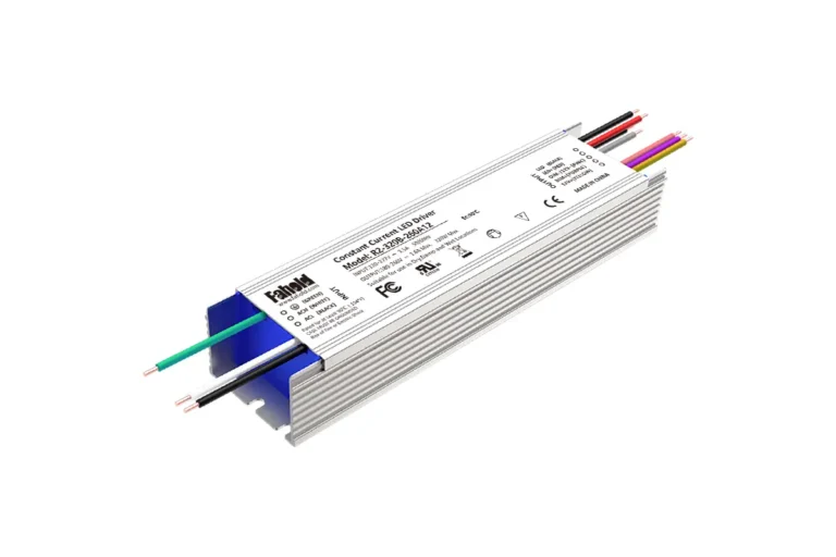
| L2-F Waterproof Dimmable LED Power Supply | 60–400W, 12V/24V constant-voltage, IP67 platform with model-dependent dimming and channel configurations | Confirm the selected model’s control method, output channel ratings and installation arrangement |
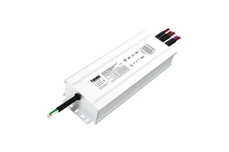
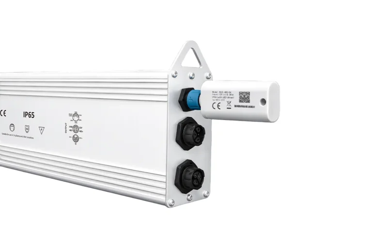
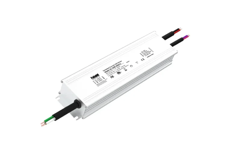
| L3 High-Power LED Sign Power Supply | 100–1200W high-power single-output platform, 12V/24V/36V/48V options, IP67/IP68 by model; non-dimmable operating platform | Verify input range, output voltage, rated current, model-specific IP rating, thermal limits and applicable approvals |
The L2-E is a reasonable candidate when installation depth is limited and a fixed-output 12V or 24V supply is required. L2-F is worth evaluating when the project needs an IP67 platform with a supported dimming option. L3 is a candidate for higher-power fixed-output loads. These are starting points for model matching, not blanket claims that every model in a series is suitable for every outdoor sign.
Use the current FAHOLD LED Sign Power Supplies range to compare available models, then confirm the selected part number against its latest datasheet before approval.
8. Information to Send with an RFQ
A supplier can make a more useful recommendation when the request includes the sign’s electrical and installation details. Sending only “IP67, 24V, 150W” may leave important compatibility questions unanswered.
| Information to provide | Details to include |
|---|---|
| LED load | Module or strip model, rated voltage, power per module or metre, quantity and total connected load |
| AC input | Site supply voltage and frequency |
| Installation environment | Indoor or outdoor position, rain exposure, cleaning method, enclosure type and expected temperature |
| Wiring layout | Approximate cable lengths, conductor size if known, branch count and location of the power supply |
| Control requirements | Fixed output or dimming; if dimming is required, specify the control method |
| Compliance needs | Target market, project or sign-system requirements, and any required listing or Class 2 status |
| Mechanical constraints | Maximum supply dimensions, mounting orientation and cable-entry requirements |
| Commercial details | Estimated quantity, sample needs and target production schedule |
Request an IP67 LED Power Supply for Your Signage Project
Send the LED specifications, total load, installation details and required approvals to FAHOLD for model matching. If the design is still being finalized, include a wiring sketch or sign drawing so output capacity, cable routing and installation constraints can be reviewed together.
Frequently Asked Questions
Does every outdoor LED sign need an IP67 power supply?
No. The required protection depends on the sign’s location, enclosure design, water exposure and applicable installation requirements. IP67 may be appropriate for some exposed installations, while another configuration may be sufficient in a protected compartment. Select the rating from the actual conditions and the product documentation.
Is IP67 suitable for a sign that is pressure-washed?
Not automatically. IP67 does not, by itself, establish resistance to high-pressure or high-temperature water jets. Check the cleaning method and the product’s stated protection conditions, and verify the connectors, cable entries and junction boxes used in the installation.
Should I use a 12V or 24V power supply for channel letters?
Use the voltage specified for the LED modules. If the sign design supports either voltage, compare current, wiring distance and module arrangement. A 24V system draws less current than a 12V system for the same power, but the module rating and the complete electrical design remain decisive.
How much extra wattage should I allow?
There is no single percentage that fits every project. Calculate the connected load, apply the project’s design allowance, then check the driver’s temperature derating curve and any per-channel limits. A nominal wattage calculation alone is not enough for a hot or enclosed installation.
Does IP67 mean the complete sign is waterproof?
No. The rating applies to the tested enclosure or product configuration. The finished sign also depends on connectors, cable entries, field wiring, junction boxes, mounting and drainage. Verify the complete installation design rather than relying on the power supply label alone.
Need Help With Your LED Power Supply Project?
Tell us what you are working on. We will review your application and recommend the most relevant FAHOLD solution.