Table of Contents
A PWM dimmable LED power supply is a power-conversion device used in a lighting system where brightness is controlled through pulse-width modulation (PWM). The term needs one important qualification: a driver that accepts a PWM control signal is not necessarily a driver that delivers PWM-switched power to the LEDs. A third arrangement uses an ordinary constant-voltage power supply followed by a separate PWM LED controller. These systems can all dim 12V or 24V lighting, but their wiring, compatibility checks, and purchasing specifications differ.
For a commercial or architectural installation, identify where the dimming happens before choosing a product. The supply, controller, LED load, and their electrical ratings must work as one system.
What Is a PWM Dimmable LED Power Supply?
PWM stands for pulse-width modulation. It is a technique that varies the proportion of time a signal or switched load is on during each repeating cycle. In an LED lighting system, changing that proportion can change the average energy delivered to the LEDs and therefore their light output.
In product specifications, however, “PWM dimmable” may describe the control interface, the output-dimming technique, or the complete low-voltage system. Those meanings should not be treated as interchangeable.
What Does PWM Mean in LED Dimming?
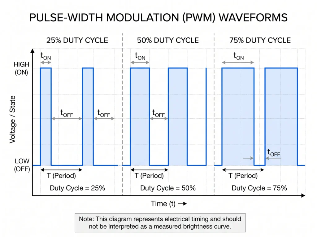
The duty cycle is the percentage of one PWM period spent in the active state. A 25% duty cycle means 25% on-time and 75% off-time; a 75% duty cycle means the opposite. PWM frequency describes how many complete cycles occur per second, expressed in hertz (Hz).
For a switched-output LED circuit, the following table illustrates the timing relationship:
| PWM duty cycle | On-time per cycle | Off-time per cycle | Electrical interpretation |
|---|---|---|---|
| 25% | 25% | 75% | Short active interval and lower average conduction |
| 50% | 50% | 50% | Equal active and inactive intervals |
| 75% | 75% | 25% | Longer active interval and higher average conduction |
| 100% | 100% | 0% | Continuously active in this idealized example |
This is a timing illustration, not a universal brightness calibration. A 25% PWM input does not guarantee precisely 25% measured luminous flux or 25% perceived brightness. The driver may process the input differently, and human brightness perception is not linear.
Does PWM Dimming Change the Output Voltage or Current?
Not necessarily in the way the term first suggests. In a 24V constant-voltage LED strip system, PWM dimming does not simply mean replacing the 24V supply with a continuously adjustable 0–24V output. A downstream PWM controller may switch the 24V supply connection to the strip on and off. An integrated dimming driver may use another internal method to translate a PWM control signal into a lower light level.
Ask two questions: Where is the PWM waveform present? And what electrical behavior does the LED load actually receive? The answer comes from the controller and driver documentation, not the word “PWM” on the product listing.
Is a PWM Dimmable Power Supply the Same as a PWM LED Driver?
In constant-voltage strip and architectural lighting, suppliers often use “LED driver” and “LED power supply” for overlapping product categories. Neither name, by itself, confirms a PWM input or PWM-switched output. A relevant specification should identify the power architecture (constant voltage or constant current), the control interface, the required signal, and the output behavior.
How Does PWM Dimming Work in an LED Power Supply?
In basic switched-load PWM dimming, an electronic switching device repeatedly connects and disconnects the LED load. The switch is turned on for a controlled fraction of each cycle. Increasing on-time generally increases average LED light output; decreasing it reduces average output. The LED is not necessarily being supplied with a continuously reduced DC voltage.
PWM is useful because a switched LED may operate near its intended instantaneous operating point during the on interval. That can help preserve color characteristics compared with some forms of current-reduction dimming, although actual performance depends on the LED, driver, waveform, and system design. Texas Instruments discusses these tradeoffs in its technical explanation of analog and PWM LED dimming.
What Happens at Low Dimming Levels?
Very low duty cycles leave little time for the LED current to reach its intended level. Driver response time, switching behavior, controller resolution, and any minimum on-time can make the actual dimming curve depart from the commanded duty cycle. A product that dims acceptably at 50% may still show unstable output, steps, or inconsistent starting behavior near its minimum setting.
PWM frequency is another design variable. A frequency that is workable for one driver/controller combination may not be supported by another. Visible flicker and stroboscopic effects also depend on more than whether a waveform is above a single threshold. For professional projects—especially museums, retail displays, and environments involving cameras or moving objects—evaluate the actual installed system at low, medium, and high output. Lutron’s application note on PWM and current-reduction dimming discusses flicker, EMI, and wiring-related considerations; its constant-current examples should not be applied automatically to a particular constant-voltage product.
PWM Control Input vs. PWM Output: Three Common System Architectures
The point at which modulation occurs changes what the project needs to purchase. Three arrangements are particularly easy to confuse.
1. Fixed-Output Power Supply with a Downstream PWM Controller
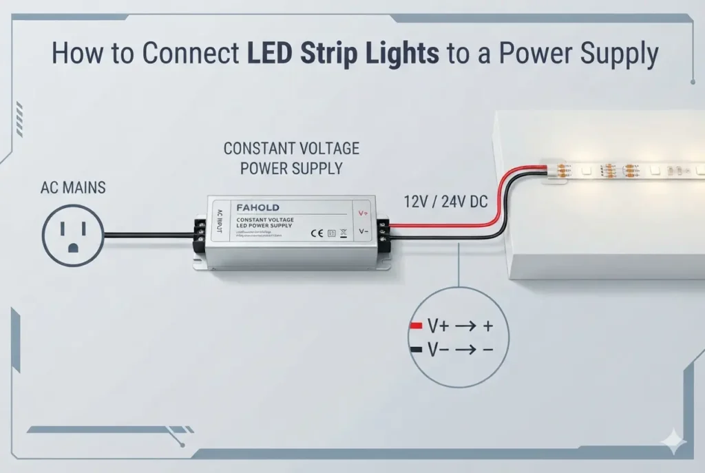
An AC-to-DC constant-voltage supply provides the rated 12V or 24V output. A separate low-voltage PWM controller sits between the supply and the LED strip and switches the load-side connection. The power supply itself may be non-dimmable, provided the manufacturer permits that downstream-controller arrangement and the complete system is correctly rated.
The controller must accommodate the DC voltage, total and per-channel current, channel count, switching behavior, and load type. It must not be treated as an accessory that can be added to any power supply without verification.
2. Dimmable Power Supply with a PWM Signal Input
In this arrangement, an external controller sends a PWM command to a dedicated dimming input on the power supply. The power supply interprets that command and manages the LED output. It may use PWM switching or another internal regulation method; a PWM input does not prove that the load output is PWM-switched.
Before connecting a controller, confirm the input’s voltage level or current characteristics, frequency range, polarity, reference/ground, wiring requirements, and any isolation conditions specified by the driver manufacturer. Do not assume that all controllers labeled “PWM” produce compatible signals.
3. Power Supply with PWM-Modulated LED Output
Some supplies directly provide a modulated output to the LEDs. The power stage and switching behavior are then part of the driver design. The LED load must be rated for the resulting waveform and applicable peak electrical conditions, not merely for a nominal 12V or 24V label.
The three approaches can be compared as follows:
| System arrangement | Where the PWM function is applied | Main compatibility checks | Common purchasing error |
|---|---|---|---|
| Fixed-output supply + external PWM controller | Between DC supply and LED load | Supply voltage, controller voltage/current, number of channels, LED load | Assuming the power supply itself needs a PWM input |
| Driver with PWM control input | At the driver’s control terminals | Signal electrical levels, frequency, polarity, wiring, driver response | Assuming a PWM input implies PWM-switched output |
| Driver with PWM-modulated output | At the LED power output | Output waveform, LED load compatibility, driver limits | Choosing from nominal wattage and voltage alone |

If the project calls for a dedicated PWM-compatible dimming supply rather than a separate downstream controller, review FAHOLD PWM-compatible LED driver options. The exact control interface still needs to be confirmed for the selected model.
How to Choose a PWM Dimmable LED Power Supply
Begin with the LED load and controller, then narrow the driver options. A useful sourcing sequence is to verify the following specifications in order.
Confirm Constant Voltage or Constant Current
Many commercial LED strips and architectural linear systems require a regulated 12V or 24V constant-voltage supply. Other LED modules may require constant-current operation. These power architectures are not interchangeable merely because both products support a form of PWM dimming. Check the LED manufacturer’s electrical rating first.
Match 12V or 24V Output to the LED Load
Select the DC output voltage printed in the LED load’s specification. A conventional 12V strip should not be connected directly to a 24V supply. At the same power, a 24V system draws approximately half the current of a 12V system, which can influence conductor sizing and distribution losses. The required voltage is still set by the LED product—not by a general preference for 24V.
Calculate the Load and Check Usable Capacity
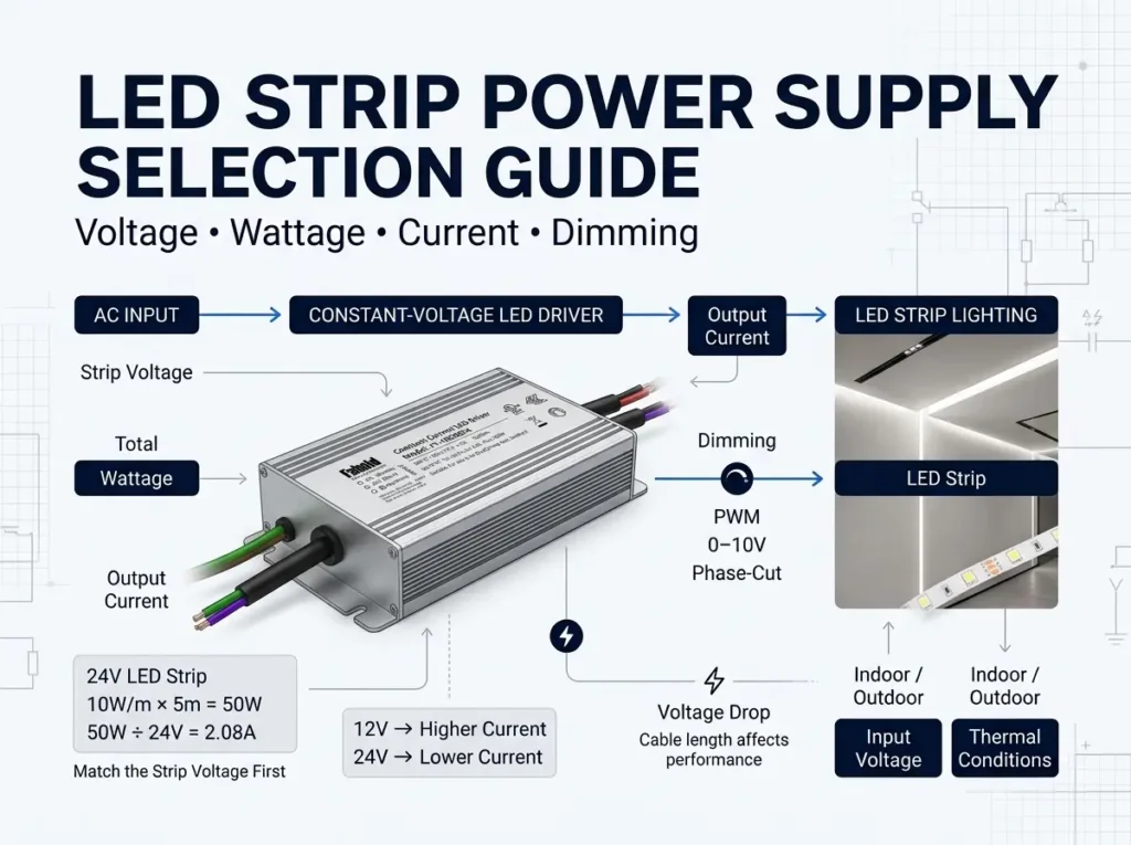
Consider a 24V architectural LED strip installation with six meters of strip rated at 10W/m:
| Calculation | Result |
|---|---|
| Connected strip length | 6m |
| Rated strip consumption | 10W/m |
| Maximum connected strip load | 6 × 10 = 60W |
| Nominal DC output voltage | 24V |
| Calculated full-load current | 60 ÷ 24 = 2.5A |
This load calculation is only the starting point. Choose a supply whose usable continuous output covers the actual load under the installation’s temperature and derating conditions. If a downstream PWM controller is used, verify that the controller and each channel can also carry the relevant current. If the power supply has multiple outputs, check each output’s independent rating rather than dividing the nameplate wattage arbitrarily.
There is no universal rule that adding exactly 20% wattage makes every installation safe or compliant. Follow the candidate manufacturer’s continuous-load, thermal, and installation requirements.

Verify PWM Signal Compatibility
A controller or building-management system may have a PWM output, but that alone does not establish compatibility with the power supply’s dimming input. Obtain the controller data and the proposed driver datasheet, then compare:
| Item to verify | Information needed | Why it matters |
|---|---|---|
| PWM interface type | Logic-level, open-drain/open-collector, or other specified format | Different outputs are not electrically equivalent |
| Signal amplitude and polarity | Controller output and driver input limits | Prevents an unsuitable or ineffective control connection |
| Frequency and duty-cycle range | Supported limits on both devices | Affects whether commands are recognized and dimming is stable |
| Minimum dimming and off behavior | Minimum light level, start behavior, dim-to-off support | Determines usability in low-light scenes |
| Wiring and isolation | Control common/reference, isolation, cable requirements | Helps avoid noise, malfunction, or unsafe connections |
| Output configuration | LED load, branch current, channel count | Confirms the intended load arrangement is supported |
For new installations, ask the driver supplier to review the actual PWM controller model and signal specification rather than describing the requirement only as “PWM dimmable.” For a shortlist of compatible constant-voltage platforms, compare PWM dimmable LED power supplies and then request model-level documentation.
Check AC Input, Enclosure, and Location
North American projects may use nominal 120Vac or 277Vac building power. That is the AC input requirement; it does not change a 24VDC LED load into a 277V output load. Confirm the rated input range of the specific supply.
Also document where the driver itself will be installed. An exterior LED strip does not automatically mean the driver must be mounted outdoors. Conversely, a driver exposed to moisture, dust, or washdown conditions needs enclosure protection and installation approvals appropriate to that location. IP ratings, electrical listings, and site conditions are separate checks.
PWM Dimming vs. 0–10V Dimming: What Is the Difference?
PWM and 0–10V describe different control-signal formats, even though a particular LED driver may support both. A conventional analog 0–10V control sends a varying DC signal level. A PWM command varies the active portion of a pulse train. The driver’s internal design then determines how that command affects the output.
| Question | PWM control input | Analog 0–10V control input |
|---|---|---|
| What carries the dimming command? | Duty cycle of a pulse signal | DC control voltage level |
| What must be matched? | Interface type, signal level, frequency, polarity | Control voltage range, source/sink behavior, wiring |
| Does the interface dictate the LED output waveform? | No | No |
| Can the interfaces be swapped without checking? | No | No |
An existing 0–10V installation cannot be assumed to accept a PWM controller, or vice versa, simply because a power supply is marketed as “dimmable.” For a broader comparison that also includes phase-cut controls, see FAHOLD Class 2 dimming comparison: TRIAC vs. 0–10V vs. PWM.
Where Are PWM Dimmable LED Power Supplies Used?
PWM-based control may be considered for low-voltage commercial lighting when the luminaires, power supply, and specified controller support the chosen arrangement. Application context matters because the most demanding condition is not always full brightness.
Commercial and Retail Lighting
Retail shelving, display cases, and architectural linear lighting often use 12V or 24V constant-voltage LED systems. Designers need to account for dimming zones, controller channels, supply location, and changes to display layouts. The exact controller/driver combination should be evaluated before units are standardized across multiple stores.
Museums and Galleries
Accent and exhibit lighting may spend long periods at low output. Low-end stability, visible or camera-detectable modulation, color presentation, and scene repeatability may be more important than the nameplate power alone. PWM’s presence is not a guarantee of flicker-free performance: sample and test the intended combination under representative operating conditions.
Hotels, Offices, and Commercial Interiors
Indirect cove and linear fixtures can form part of a broader lighting-control specification. Before specifying a PWM-input supply, confirm whether the existing control system truly provides the required PWM signal or instead uses 0–10V, phase-cut, DALI, or another interface. Matching the control architecture prevents avoidable site rework.
Architectural Facades and Landscape Lighting
Building outlines, facade details, and some landscape linear-lighting systems need careful control of cable runs, supply placement, environmental exposure, and service access. A waterproof power supply can be appropriate when the driver is installed in a location that requires it, but the complete outdoor installation must still meet applicable electrical, mechanical, and environmental requirements.

Common PWM Dimming Problems and How to Troubleshoot Them
When a PWM-controlled lighting system behaves poorly, isolate the driver, controller, wiring, and LED load instead of replacing the supply immediately. A qualified technician should verify the control and output conditions using appropriate instruments and safe procedures. Do not perform exposed mains measurements without the required qualifications.
| Symptom | Possible causes | Practical verification |
|---|---|---|
| Visible flicker or bands on camera | Modulation frequency, driver response, ripple, or controller/load interaction | Test several dim levels; review actual waveform and equipment compatibility |
| Unstable output near minimum brightness | Controller resolution, minimum on-time, incompatible PWM command, or driver limits | Verify supported duty-cycle/frequency range and minimum dimming specification |
| LEDs remain at full brightness | Wrong control terminals, unsupported input type, missing reference, or incorrect setup | Check the actual terminal diagram and command signal with the correct equipment |
| LEDs do not turn fully off | Control behavior or driver dim-to-off limitations | Confirm whether zero command means minimum output, standby, or complete off |
| Uneven brightness between runs | Voltage drop, branch imbalance, conductor losses, or different LED loads | Measure branch conditions and compare run lengths, conductors, and feed points |
| Audible noise | Switching interaction, component vibration, or operating-point effects | Test the specified controller-driver-load combination across the dimming range |
For persistent flicker, capture both the intended PWM command and the actual light/output behavior when possible. The two may differ. Long control or load wiring can also affect electrical behavior; Lutron’s technical discussion of PWM and wiring parasitics illustrates why a lab-tested component should not be treated as proof of full-system performance.
An installation review should record the controller model, driver model, LED load, cable lengths, frequency and control settings, and the dimming level at which the issue occurs. That record is much more useful to engineering support than “the PWM driver flickers.”
PWM-Compatible LED Power Supply Options for Commercial Projects
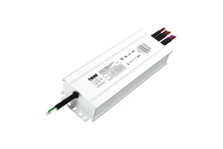
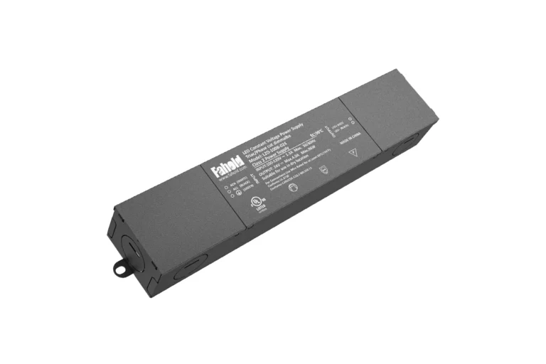
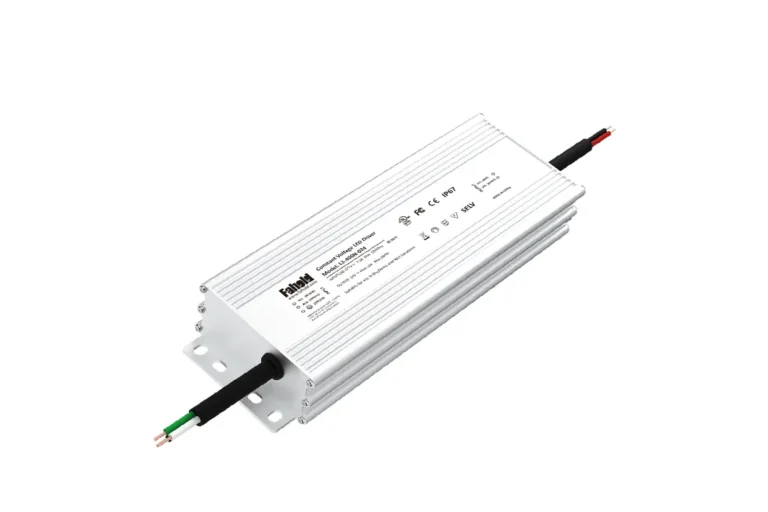
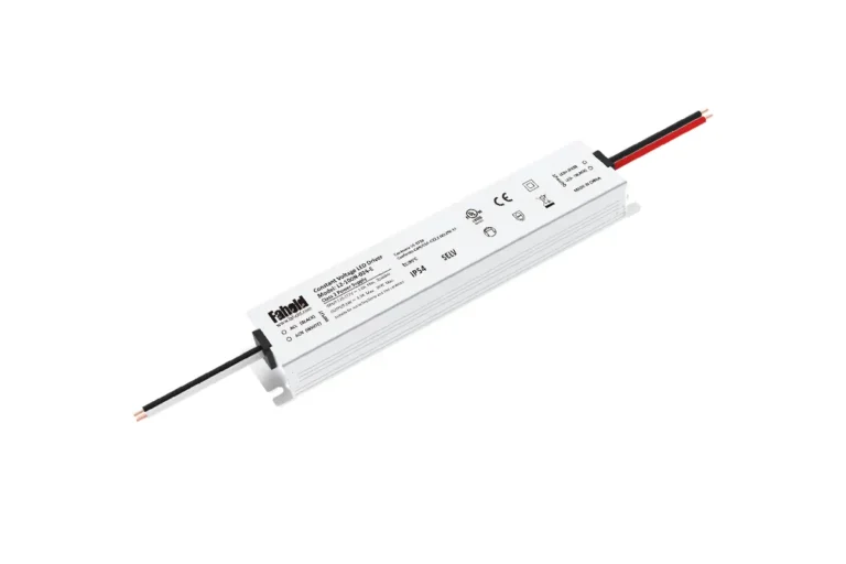
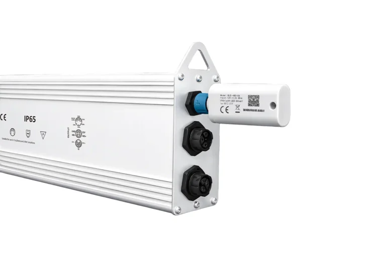
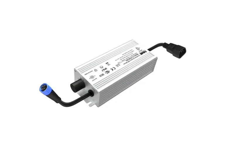
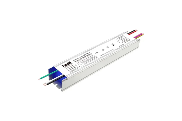
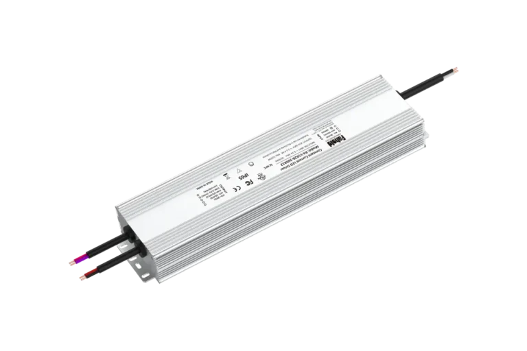
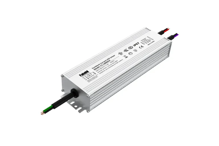
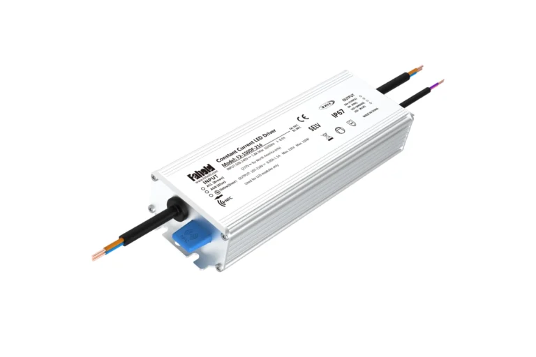
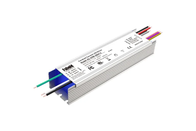
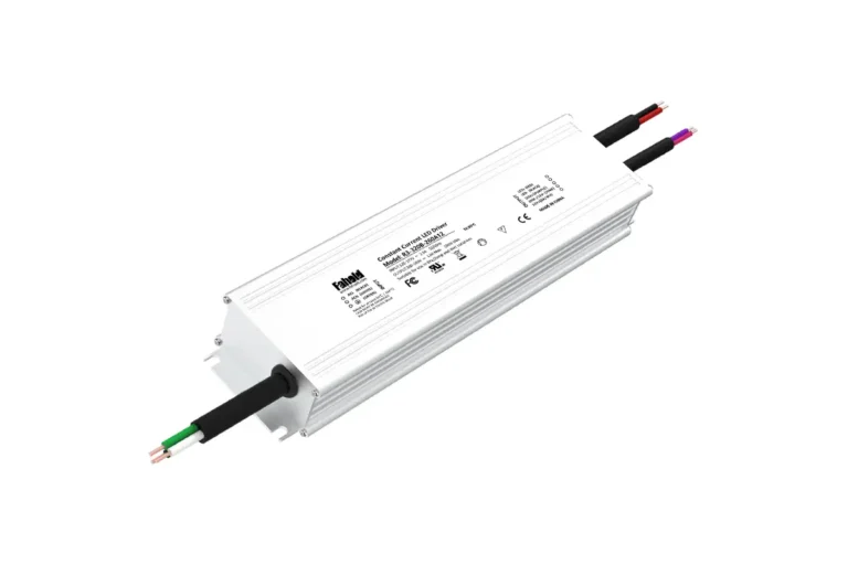
For 12V and 24V constant-voltage architectural lighting, FAHOLD relevant starting platforms are the L2-A enclosed series and the L2-F waterproof series. The two families should be compared by installation environment, enclosure construction, required output, channel arrangement, and the PWM control interface of the exact dimmable configuration. A series-level mention of PWM support is not blanket approval for every SKU or every controller.
| Selection factor | FAHOLD L2-A | FAHOLD L2-F |
|---|---|---|
| Platform role | Enclosed, junction-box-oriented constant-voltage supply | Waterproof constant-voltage supply |
| Nominal AC input platform | 100–277Vac | 100–277Vac |
| Constant-voltage options | 12V / 24V | 12V / 24V |
| Platform ingress-protection positioning | IP65 | IP67 |
| PWM-related capability | Model/configuration-dependent dimming input option | Model/configuration-dependent dimming input option |
| Primary installation question | Is the enclosed wiring arrangement suitable? | Does the driver location require verified waterproof construction? |
Review the L2-A enclosed LED power supply series when a protected junction-box-style architecture suits the project. Review the L2-F waterproof LED power supply series when the driver’s own installation environment requires higher ingress protection. Neither IP rating replaces a check of the exact product listing, certifications, control interface, output limits, or installation instructions.
If the requirement is already defined, the quickest next step is a model-level review using output voltage, AC input, usable power, channel count, enclosure protection, and the intended controller. The series overview establishes a starting point; the selected SKU’s documentation determines the final match.
PWM Dimmable LED Power Supply FAQs
Do All Dimmable LED Power Supplies Support PWM?
No. “Dimmable” may refer to 0–10V, phase-cut, PWM input, another interface, or a combination. Confirm the actual dimming inputs for the model and configuration being ordered.
Can I Use a PWM Dimmer with a Non-Dimmable Power Supply?
Sometimes a suitable constant-voltage, fixed-output supply can feed an external low-voltage PWM controller. This does not mean a non-dimmable supply can receive PWM or phase-cut control directly at its AC input. Both the supply’s permitted load behavior and the downstream controller’s voltage/current ratings must be verified.
Are PWM Dimmable Power Supplies Available for Both 12V and 24V LEDs?
Yes, compatible 12V and 24V constant-voltage systems can use PWM-related dimming arrangements. Match the supply output to the LED load and verify the control interface separately; 12V and 24V versions are not interchangeable.
Does PWM Dimming Always Cause Flicker?
PWM involves modulation, but whether users observe flicker or stroboscopic effects depends on the actual waveform, frequency, duty cycle, lighting environment, and viewing or camera conditions. Do not treat “flicker-free” as a universal property without the relevant system test or verified performance data.
Can Any PWM Controller Work with a PWM Dimmable Driver?
No. PWM control interfaces differ in electrical level, frequency, polarity, output configuration, reference, and isolation requirements. Compare the controller specification with the exact driver’s control-input documentation before connecting them.
What Should I Send a Manufacturer for PWM Driver Selection?
Provide the AC input, LED load type, 12V/24V requirement, maximum connected wattage and current, number of branches or channels, controller make/model and PWM signal details, target dimming range, installation environment, required certifications, target market, and expected quantity. If replacing a supply, include the existing model and its wiring or datasheet.
From PWM Theory to a Verified Project Specification
A successful specification identifies which device receives the dimming command, which device switches or regulates power, and what the LED load is designed to accept. Once those three questions are answered, voltage, load, control compatibility, enclosure, and model documentation can be checked without guessing from marketing labels.
For a commercial lighting project, review FAHOLD PWM dimmable LED power supplies and request confirmation against the intended controller and load. Share the project requirements and relevant datasheets for model matching, sample evaluation, and quotation.
Find the Right LED Power Supply for Your Project
Share the core electrical and application requirements. We will narrow the available FAHOLD platforms to the options most relevant to your project.