Table of Contents
A 24V power supply can be electrically suitable for a display cabinet and still create problems once the cabinet is assembled. The unit may not fit behind the rear panel, the upper shelves may receive a different voltage from the lower shelves, or the supply may run hotter than expected inside a closed compartment.
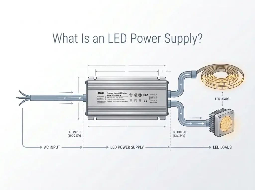
Those issues are easier to prevent during cabinet design than to correct after production. Start with the LED product specification, calculate the load for each lighting zone, and then plan the power supply location, cable routes and thermal conditions. The selected supply must match the complete installation, not just the number printed beside “24V”.
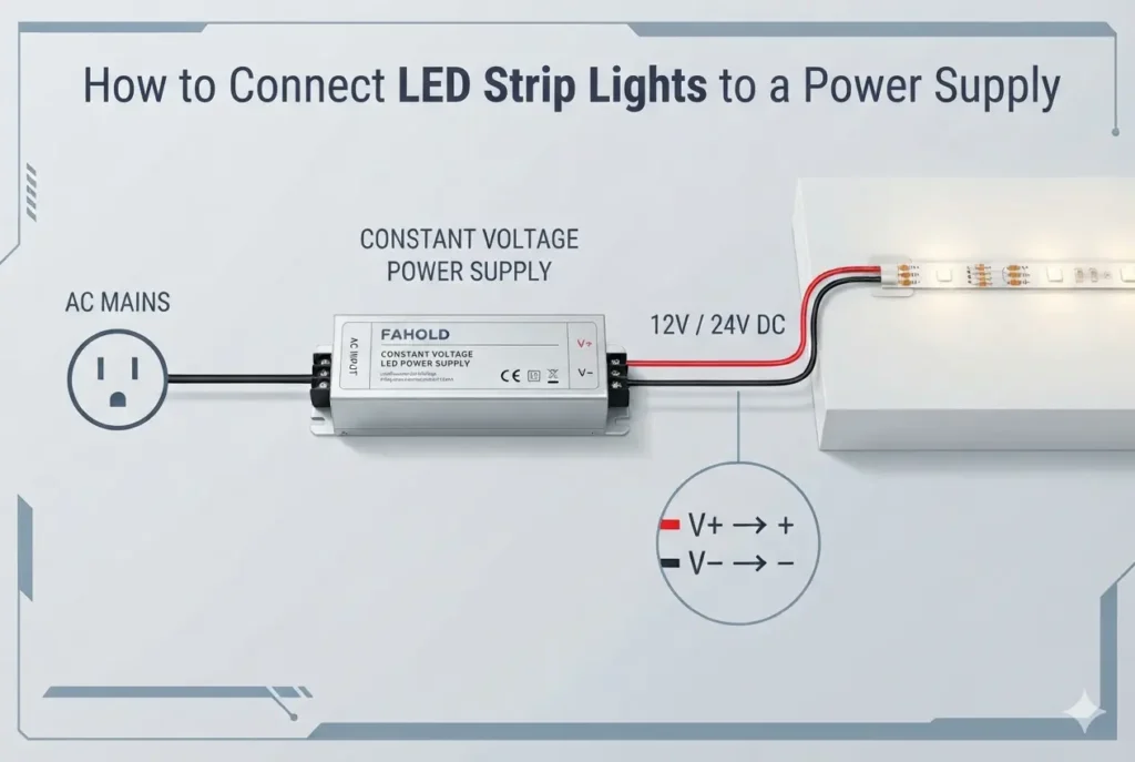
This guide focuses on 24V constant-voltage LED systems used in retail display cabinets, glass showcases and illuminated shelving. If the fixture uses an LED module with an integrated driver or a constant-current input, follow that fixture manufacturer’s electrical specification instead of assuming it can connect directly to a 24V constant-voltage source.
Quick Selection Check
| Design area | What to confirm | Evidence to keep |
|---|---|---|
| LED system | 24V DC input and constant-voltage compatibility | LED strip, bar or module datasheet |
| Connected load | Total watts and current for every shelf or zone | Load schedule and calculation |
| Supply architecture | One centralized supply, separate supplies or a multi-output model | Cabinet wiring diagram |
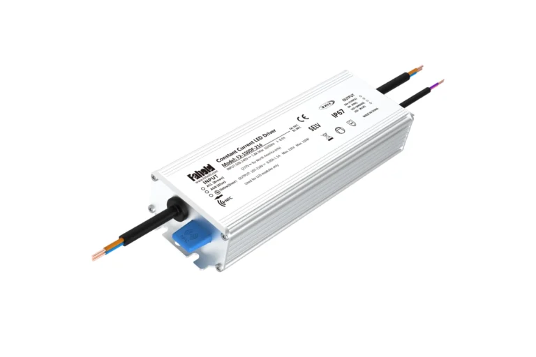
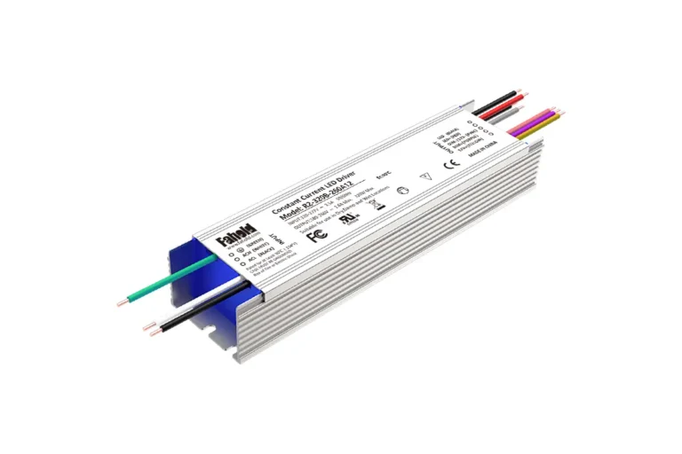
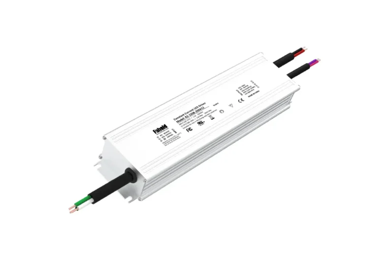
| Physical fit | Length, width, height, mounting and cable-exit clearance | Dimension drawing and cabinet layout |
| Thermal conditions | Ambient temperature, enclosed-space temperature and derating | Driver datasheet and thermal assessment |
| Wiring | Branch current, cable length, conductor size and connector ratings | Wiring plan and voltage-drop check |
| Control | Fixed output or compatible dimming method | Controller and driver documentation |
| Compliance | Listings and requirements applicable to the finished fixture and market | Model-specific certification records |
A quick checklist helps screen candidate products. It does not replace checking the exact model number, wiring arrangement and operating conditions.
1. Confirm That the Cabinet Uses a 24V Constant-Voltage LED System
Before comparing power supplies, identify the actual light source. Retail display cabinets may use flexible LED strips, rigid linear bars, small LED modules or complete luminaires with their own internal electronics. Their appearance may be similar, but their electrical inputs are not necessarily interchangeable.
Read the LED specification, not just the product label
For each lighting component, record its rated input voltage and whether the input is DC, its constant-voltage or constant-current requirement, power consumption per metre or module, permitted input range, and whether a separate controller or driver is required.
A 24V constant-voltage strip is designed to operate from a regulated 24V DC source within the limits stated by its manufacturer. A constant-current LED module, by contrast, requires a driver that regulates current within its specified output-voltage range. Connecting it to a generic 24V supply can produce incorrect operation or damage.
Do not infer compatibility from the words “24V LED” alone. Check the wiring diagram and datasheet for the exact LED product being installed.
Account for mixed lighting components
A cabinet may combine vertical accent lighting, shelf-edge strips and a top light. If all components are rated for the same 24V constant-voltage system, they may be supplied from a common source if total capacity, branch wiring and control requirements allow it. If one component has a different input requirement or an integrated driver, treat it as a separate load and follow its own installation instructions.
The electrical schedule should identify every load before the power supply is specified. This avoids selecting a supply around the main shelf strips and overlooking a smaller but electrically different lighting component.
2. Calculate the Total Load Across Every Shelf and Lighting Zone
For a multi-shelf cabinet, calculate the load from the actual strip length or module count. Do not estimate from the cabinet’s outside dimensions: the illuminated length may be shorter, and different shelves may use different LED products.
Work from the installed LED length
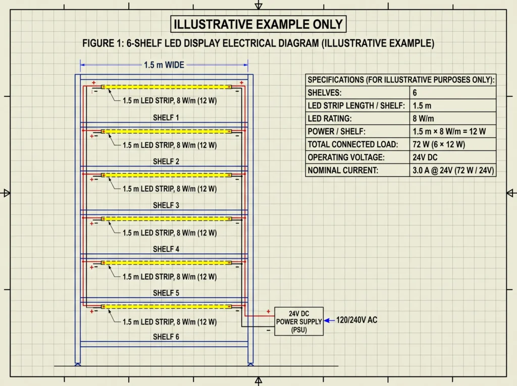
Consider a cabinet with six shelves. Each shelf uses a 1.5 m LED strip rated at 8 W/m.
| Load item | Calculation | Result |
|---|---|---|
| Number of strips | 6 | 6 strips |
| Length per strip | 1.5 m | 1.5 m |
| Power per metre | 8 W/m | 8 W/m |
| Power per strip | 1.5 m × 8 W/m | 12 W |
| Total connected load | 6 × 12 W | 72 W |
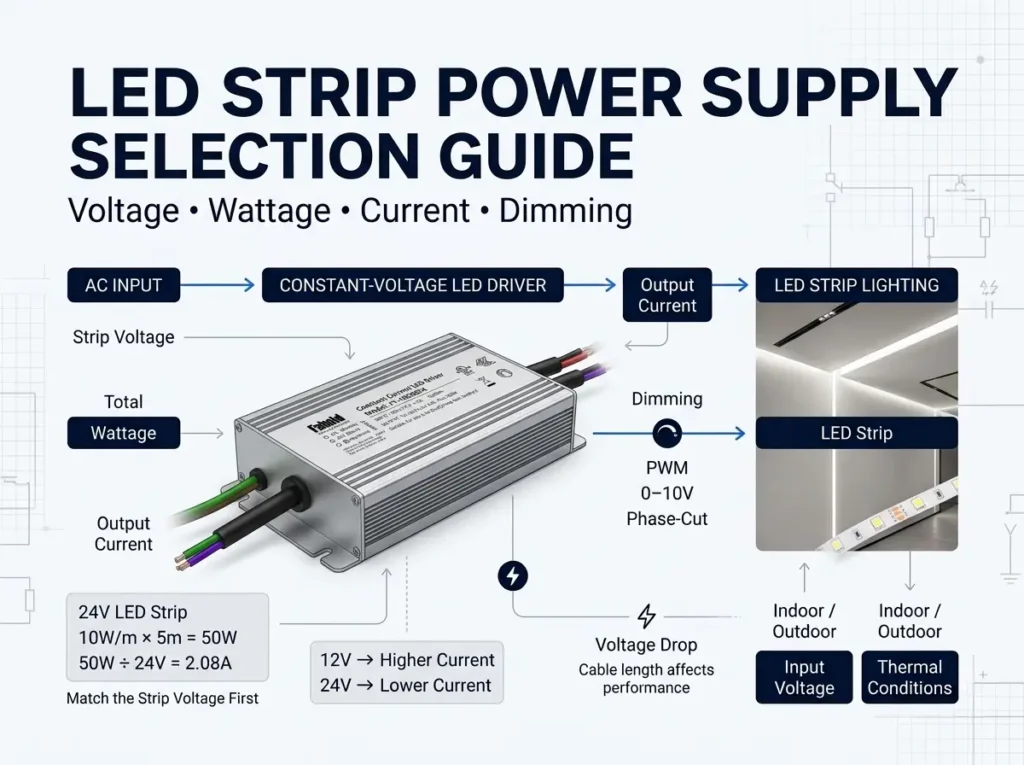
| Total current at 24V | 72 W ÷ 24 V | 3 A |
For this example, the connected LED load is 72 W and the nominal current is 3 A at 24V DC. These are calculated values based on the stated strip rating, not measured operating results.
Select capacity using the project’s design conditions
The power supply should not be selected by matching its nameplate wattage exactly to the calculated load without checking the manufacturer’s operating conditions. Consider the intended continuous load, ambient temperature, enclosure temperature, input voltage and any output derating specified for the model.
For illustration, if a project specification limits normal connected load to 80% of the supply’s rated capacity, the capacity calculation would be:
Required rated capacity = 72 W ÷ 0.80 = 90 W.
The 80% figure here is an example project design criterion, not a universal rule for every LED installation. Use the project specification and the power supply manufacturer’s derating data to establish the actual selection margin. If the supply is installed in a warm, enclosed compartment, its usable output may be lower than the headline rating.
Also check current limits. A supply can have sufficient total wattage while a particular output terminal, connector or branch is overloaded. The wiring schedule should show both total load and the current assigned to each branch.
3. Decide Whether to Use One Supply or Multiple Supplies
The choice between a centralized supply and separate supplies affects cable length, service access, fault isolation and cabinet assembly. There is no single arrangement that suits every display fixture.
Centralized supply for one cabinet
A single supply can be practical when the cabinet has a suitable service compartment and the LED branches can be routed without excessive cable length. It reduces the number of power units and can simplify replacement.
The trade-off is that more current may travel through the distribution wiring from one location. Each branch still needs to be sized for its own current and cable run. A wiring diagram should identify the supply location, distribution point, branch routes and connector ratings.
Separate supplies for independent cabinets or zones
Separate supplies may make sense when cabinets are physically distant, need independent switching, or must remain operational if another cabinet is serviced. They can shorten low-voltage cable runs and make fault isolation more straightforward.
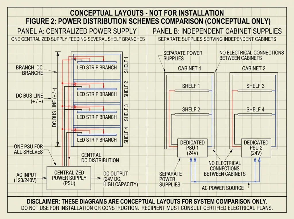
The additional units require space, AC distribution, mounting provisions and service access. If several cabinets share one AC circuit, the electrical designer must also consider the combined input load and applicable installation requirements.
Multi-output supplies are not automatically multi-zone dimmers
A power supply with multiple output terminals may provide convenient distribution, but that does not necessarily mean each output can be controlled independently. Check whether the outputs are electrically separate, whether each has its own current limit, and whether the model supports independent control.
| Supply arrangement | When it may fit | Points to verify |
|---|---|---|
| One centralized supply | Several shelves in one cabinet with a practical distribution route | Total load, branch current, cable length and service access |
| One supply per cabinet | Multiple cabinets or independently serviced fixtures | Unit count, mounting space, AC feed and replacement access |
| Multiple-output supply | Several branches need organized output connections | Per-output current limit, total capacity and output isolation |
| Separate supplies by lighting zone | Zones require independent power or control | Control architecture, switching method and wiring separation |
For a cabinet OEM, decide the supply arrangement while the cabinet wiring and service compartment are still being designed. Changing from one centralized unit to several smaller units late in production can affect the enclosure, harness, bill of materials and assembly process.
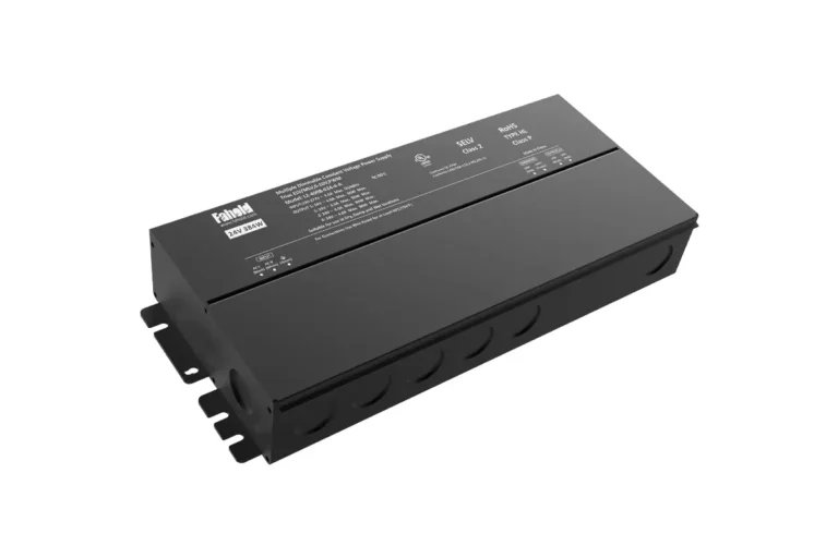
4. Check Power Supply Dimensions Before Cabinet Assembly
A power supply that meets the electrical specification may still be unsuitable if it cannot be mounted securely or serviced after the cabinet is installed. This is particularly relevant to glass showcases, jewelry cabinets and slim retail fixtures where available space is often defined by the frame and rear panel.
Check the complete installation envelope
Compare the manufacturer’s dimension drawing with the cabinet design. Allow for more than the body dimensions:
- Space required for AC and DC cable bends.
- Connector and terminal access.
- Mounting holes, brackets and fasteners.
- Clearance required by the manufacturer for cooling.
- Access for inspection or replacement.
- Separation from heat-sensitive materials and other components.
Do not assume that a supply can be mounted in any orientation simply because it fits. Follow the installation instructions for mounting direction, ventilation and clearance. A tightly enclosed compartment may also change the thermal conditions under which the supply can deliver its rated output.
Choose compactness without sacrificing serviceability
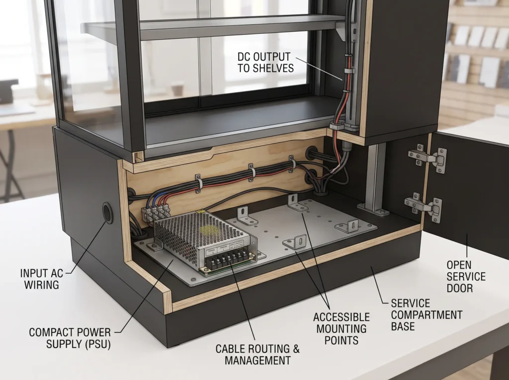
Slim or compact supplies can help when the cabinet has limited depth. However, the smallest body is not automatically the best option. A unit that leaves no room for cable termination or cannot be reached without dismantling the cabinet can increase production and maintenance costs.
For repeat OEM production, freeze the approved power supply dimensions and cable-exit arrangement in the cabinet drawing. If the supplier changes the model or enclosure revision, recheck mechanical fit before releasing the next production batch.
| Mechanical item | What the cabinet designer should verify |
|---|---|
| Length, width and height | The body fits within the allocated compartment |
| Mounting method | Bracket, screw or other approved fixing arrangement |
| Cable exit | Conductors can route without sharp bends or interference |
| Terminal access | Connections can be completed and inspected safely |
| Cooling clearance | Required spacing and airflow are maintained |
| Service access | The unit can be inspected and replaced without unnecessary disassembly |
5. Manage Heat Inside Enclosed Display Cabinets
A retail store may be maintained at a comfortable room temperature, but the space around a power supply inside a cabinet can be warmer. Heat from LED strips, nearby electronics, lighting drivers and restricted airflow can accumulate in a small compartment.
This matters because a power supply’s rated output may depend on ambient temperature and mounting conditions. Some models require output derating above a specified temperature. Others specify installation clearances or restrictions on enclosed use.
Assess the temperature where the supply will operate
Do not use the store’s thermostat setting as the only temperature input. Consider the actual compartment location, cabinet materials, ventilation openings, nearby heat sources and the cabinet’s operating schedule.
Where the design is uncertain, build a representative cabinet section and measure the temperature around the supply after the lighting has operated long enough to reach a stable condition. Record the measurement location and test conditions. A reading taken in the open store aisle will not describe the temperature inside a closed power compartment.
Apply the model-specific derating curve
Review the selected supply’s datasheet for its rated operating-temperature range, output derating versus ambient temperature, mounting-orientation restrictions, required clearance and any limitations on enclosed installation.
If the manufacturer’s curve reduces the permitted output at the expected temperature, use that reduced capacity in the load assessment. Do not compensate for a thermal limitation by assuming that a higher nominal wattage model will fit or operate correctly; verify the larger model’s dimensions and thermal requirements as well.
A practical cabinet review should consider the LED load and power supply together. Moving the supply away from a warm LED compartment, adding a suitable ventilation path or using a different distribution arrangement may be more effective than simply increasing the wattage rating.
6. Plan Wiring to Keep Brightness Consistent Across Shelves
Uneven brightness is often treated as an LED quality problem, but the cause can be electrical. Long low-voltage cable runs, undersized conductors, poor connections and unequal branch loading can create different voltage conditions at different shelves.
Calculate each branch rather than only the total load
The 72 W example above draws 3 A in total at 24V. That does not mean every cable carries 3 A. If the six shelves are wired as six separate branches from a distribution point, each branch carries the current of its own strip, subject to the actual wiring and control arrangement.
For one 12 W strip at 24V, the nominal branch current is:
Branch current = 12 W ÷ 24 V = 0.5 A.
The cable between the supply and the distribution point may carry the combined current, while each shelf branch carries its own load current. Size each section of wiring for the current it actually carries, its length, installation conditions and applicable electrical requirements.
Check voltage at the farthest LED load
Use the conductor resistance, cable length and branch current to estimate voltage drop. Then compare the expected voltage at the LED input with the LED manufacturer’s permitted operating range. For a prototype or production sample, measure voltage at the supply terminals and at the farthest LED connection while the cabinet is operating under a representative load.
A 24V system draws less current than a 12V system for the same power. This can reduce resistive cable losses when conductor resistance is unchanged, but it does not eliminate voltage drop. Long runs and poor connections still need attention.
| Observed issue | Possible electrical cause | What to inspect |
|---|---|---|
| Upper shelves appear brighter than lower shelves | Different cable lengths or branch resistance | Voltage at each shelf and the branch wiring route |
| One shelf is dimmer than the others | Loose connector, damaged conductor or unequal load | Terminations, connector condition and strip rating |
| Brightness changes when all shelves are switched on | Supply capacity, common feeder drop or overloaded distribution point | Supply output, feeder current and voltage at the distribution point |
| Intermittent flicker on one shelf | Intermittent connection or a control issue | Connectors, cable strain and controller wiring |
Avoid raising the supply voltage to compensate for a low reading at the far end unless the supply is designed for adjustment and the LED manufacturer permits the resulting voltage at every load. Increasing the voltage at the source may overdrive the strips closest to it. Correct the cable size, distribution point, connection or branch layout instead.
7. Verify Dimming and Lighting Control Compatibility
Some display cabinets run at a fixed brightness. Others need dimming to suit the merchandise, store environment or operating schedule. Establish the control requirement before selecting the power supply because “dimmable” does not describe one universal interface.
Match the controller to the driver
If the cabinet uses PWM dimming, confirm that the selected supply or downstream controller supports the required PWM arrangement and signal characteristics. If the project uses 0–10V, check the control input specification, wiring method and controller compatibility. DALI or another digital control system requires equipment designed for that interface; it should not be assumed to work with a driver that only supports analog dimming.
Also establish whether dimming is required for the whole cabinet or for separate zones. A single dimming channel may adjust all connected shelves together. Independent shelf control requires a compatible multi-zone architecture, not simply multiple output terminals.
Test the operating range that the cabinet will actually use
For a sample cabinet, test full output, intermediate settings and the lowest intended brightness. Look for flicker, unexpected shutdown, delayed response, uneven brightness between branches and behavior when power is restored. If the cabinet uses several supplies or controllers, test them together rather than approving each unit in isolation.
If the display does not require dimming, a correctly specified non-dimmable supply may be the simpler choice. Avoid paying for a control feature that the fixture does not use, but do not remove a required control function merely to simplify the power supply selection.
8. Verify the Product Before Approving OEM Production
A prototype that lights up is only the first approval step. Before releasing a power supply for repeat cabinet production, confirm the exact model, documentation and installation arrangement.
| Approval item | What to request or verify |
|---|---|
| Electrical ratings | AC input range, 24V DC output, rated current and total power |
| Load compatibility | Constant-voltage operation and compatibility with the specified LED products |
| Protection functions | Model-specific short-circuit, overload, overvoltage and overtemperature protection details |
| Thermal performance | Operating-temperature range and derating curve |
| Mechanical fit | Current dimension drawing, mounting method and cable-exit details |
| Dimming | Supported interface, wiring diagram and compatible controller requirements |
| Safety approvals | Current listing or certification records for the exact model and intended market |
| Production control | Approved part number, revision identification and agreed inspection documentation |
For North American projects, do not treat an IP rating as an electrical safety approval. The relevant requirements depend on whether the item is a component, a finished sign or part of a complete retail fixture, as well as the installation and approval route. Confirm applicable requirements with the project’s responsible electrical professional, certification body or local authority having jurisdiction. If a UL or ETL listing is specified, verify the exact model and the scope of the listing rather than relying on a general supplier statement.
For OEM production, retain the approved datasheet, dimension drawing, wiring diagram and sample evaluation record with the cabinet’s bill of materials. If the supplier proposes a substitute, compare the full electrical and mechanical specification before accepting it. A replacement with the same 24V output may still differ in dimensions, control behavior, protection functions or approvals.
9. Information to Include in an RFQ
A request that says only “24V, 100W” leaves too many questions unanswered. Provide enough detail for the supplier to match the power supply to the cabinet rather than recommending a unit from wattage alone.
| RFQ information | Details to provide |
|---|---|
| Display type | Jewelry cabinet, cosmetic display, glass showcase, illuminated shelving or other fixture |
| LED product | Strip, rigid linear bar, module or complete luminaire; include manufacturer and model if available |
| Electrical input | Required 24V DC constant-voltage input, or the actual specified input for the selected light source |
| Connected load | Strip length, module quantity, watts per metre or unit, and total connected watts |
| Cabinet layout | Number of shelves, lighting zones and cabinets to be powered |
| Supply arrangement | Centralized, separate per cabinet or separate by zone |
| Installation space | Maximum available length, width and height; mounting and cable-exit constraints |
| Thermal conditions | Enclosure type, ventilation, expected internal temperature and operating schedule |
| Control | Fixed output or dimming; specify PWM, 0–10V, DALI or other required interface |
| Compliance | Destination market and project-specific listing or certification requirements |
| Commercial details | Sample quantity, estimated production quantity and target schedule |
Request a 24V LED Power Supply for Your Display Cabinet Project
Send the LED datasheet, cabinet layout, connected-load calculation and available installation dimensions to FAHOLD. If the cabinet is still at the design stage, a drawing showing shelf positions, cable routes and the proposed power supply compartment will help narrow down suitable models before the prototype is built.
Frequently Asked Questions
Why are 24V LED power supplies commonly used in retail display cabinets?
Many LED strips and linear lighting products are available in 24V constant-voltage versions. At the same power, a 24V system draws less current than a 12V system, which can help with wiring losses across distributed shelf runs. The LED product’s rated input voltage must still determine the supply voltage.
How do I calculate the power supply size for a multi-shelf display cabinet?
Calculate each shelf’s load from its installed LED length and rated watts per metre, or from the number and wattage of modules. Add the loads for all shelves and zones, convert the total watts to current using the 24V output, and then apply the project’s design allowance and the selected supply’s temperature derating requirements.
Can one 24V power supply power multiple display cabinets?
It can if the combined load is within the supply’s usable output capacity and the distribution wiring, branch protection, connectors and installation requirements are suitable. Consider cable distance, independent switching, service access and what happens if the shared supply fails. Separate supplies may be more practical for cabinets that are far apart or independently controlled.
How do I prevent uneven brightness across multiple shelves?
Use a wiring plan that accounts for branch current, cable length, conductor resistance and connector quality. Measure voltage at the supply and at the farthest LED connection under load. If readings differ more than the LED product permits, review conductor size, branch layout and distribution points rather than raising the source voltage without checking every connected strip.
What should I consider when installing a power supply inside an enclosed display cabinet?
Check the available mounting space, cable access, ventilation, ambient temperature inside the compartment and the supply’s model-specific derating curve. Make sure the unit can be inspected and replaced, and follow the manufacturer’s mounting and clearance instructions. A supply that fits physically may still be unsuitable if its required cooling conditions cannot be maintained.
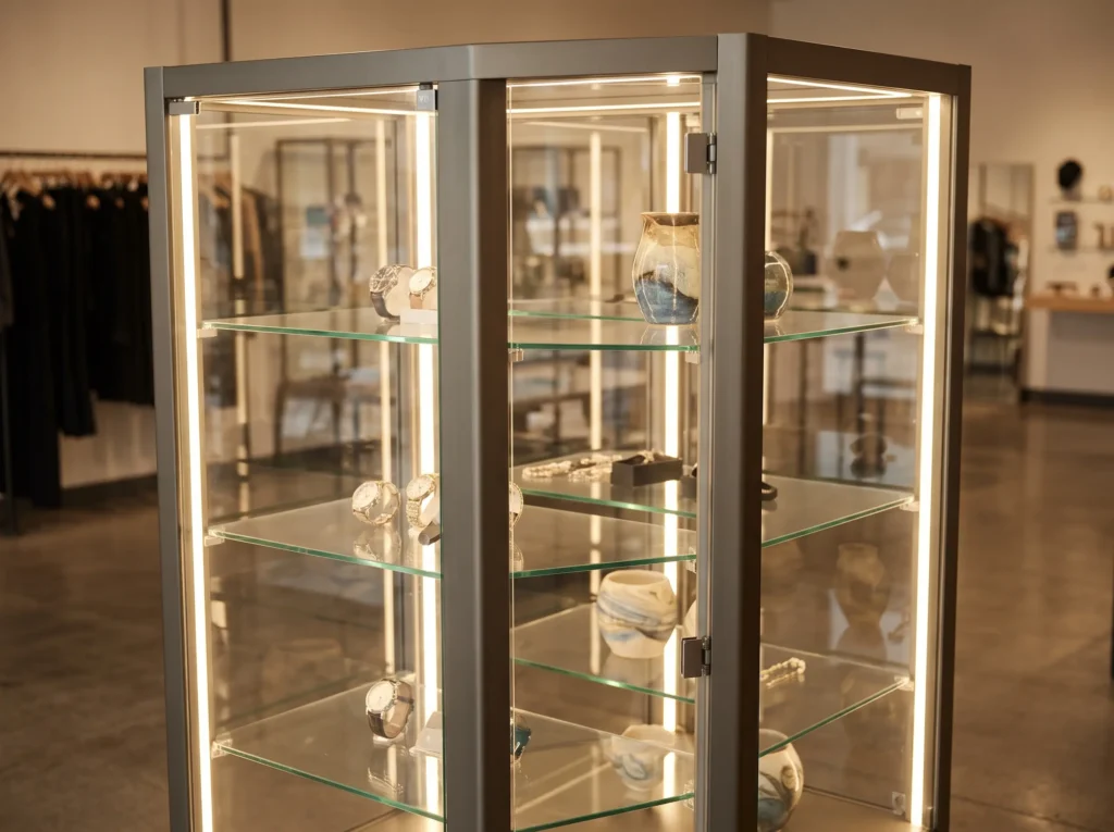
Image 1: 24V LED Lighting Inside a Multi-Shelf Display Cabinet
- Placement: After the introduction.
- Filename:
24v-led-power-supply-retail-display-cabinet.webp - Alt text:
24V LED lighting installed across multiple shelves inside a retail glass display cabinet
Image 2: Multi-Shelf LED Load Calculation
- Placement: Section 2.
- Filename:
retail-display-cabinet-led-load-calculation.webp - Alt text:
Multi-shelf retail display cabinet LED load calculation showing six 24V LED strips
Image 3: Centralized and Distributed Power Supply Layouts
- Placement: Section 3.
- Filename:
retail-display-cabinet-power-supply-distribution.webp - Alt text:
Comparison of centralized and separate 24V power supply layouts for retail display cabinets
Image 4: Power Supply Installation Space and Cable Routing
- Placement: Section 4.
- Filename:
display-cabinet-led-power-supply-installation-space.webp - Alt text:
Compact LED power supply mounting area with cable routing and service clearance inside a display cabinet
Need Help With Your LED Power Supply Project?
Tell us what you are working on. We will review your application and recommend the most relevant FAHOLD solution.