Table of Contents
A 24V LED driver and a 0–10V controller can both meet their individual datasheet specifications and still fail to deliver the dimming behavior a project requires. The system needs to be evaluated as a combination of driver, LED load, controller, wiring and operating conditions—not as a list of separately compliant components.
Before approving a 24V 0–10V constant-voltage driver for a commercial lighting project, confirm that the output matches the LED load, the control interface is compatible, the full dimming range behaves as required, and the system remains stable under representative load and installation conditions.
Use the following sequence as a starting point:
- Define the project’s acceptance criteria before testing.
- Verify the electrical load and 24V output requirements.
- Check the controller-to-driver interface and control wiring.
- Test the full dimming range with the actual LED load.
- Repeat key tests with representative branch lengths, multiple drivers and operating conditions.
- Record results, deviations and the final approval decision.
This guide focuses on 24V constant-voltage LED systems controlled by a 0–10V interface. A 24V output rating does not, by itself, mean a driver supports 0–10V dimming. Likewise, a driver with a 0–10V control input may be constant-current rather than constant-voltage. Verify both requirements on the exact model.
Quick Compatibility Check
| Compatibility area | What must match or be verified | Evidence to keep |
|---|---|---|
| Output system | 24V DC constant-voltage output and adequate current/power capacity | Driver datasheet and load calculation |
| Control interface | Exact 0–10V interface behavior, polarity, and controller/driver electrical requirements | Both product datasheets and control-terminal measurements where needed |
| LED load | Actual strip/module model, total load, branch current, and wiring | LED specifications and branch calculation |
| Dimming performance | Full, intermediate, low-end, transition, and off behavior required by the project | Completed dimming test record |
| Project conditions | Number of drivers per zone, cable layout, temperature, enclosure, and certification needs | Wiring layout, installation instructions, and approval records |
Use this table as a screening checklist, not as proof of compatibility. A final decision requires the exact product combination to meet the project’s documented acceptance criteria.
1. Define the Project Requirements Before Testing
A test is only useful when the team knows what counts as a pass. Set the requirements before connecting the sample, rather than deciding after a test result appears.
Confirm the LED load and the intended application
Record the LED strip or module manufacturer, part number, rated voltage, power per unit length or module, total connected length, and planned branch layout. Confirm that the load is designed for 24V DC constant-voltage operation. If the fixture instead requires constant current, stop and select a driver architecture that matches the fixture specification.
Also document the actual installation: office cove lighting, linear strip lighting, display lighting or another application. Installation details can affect cable lengths, enclosure choice, thermal conditions and how many loads share a driver or control zone.
Define the required dimming behavior
“Dimmable” is not a complete acceptance specification. Confirm what the project expects:
- The required minimum light output or minimum stable dimming level.
- Whether the system must fade smoothly or can use discrete control steps.
- Whether 0V on the control input must turn the light off, or whether separate switching is required.
- Whether multiple fixtures must dim consistently in the same control zone.
- Whether the system must recover to a defined state after power interruption.
- Any project-specific flicker, noise, start-up or visual-uniformity requirements.
Do not assign a universal minimum dimming percentage or flicker limit to every driver. Use the project specification, applicable standards and the selected driver’s published performance data.
| Requirement to define | Record before testing | Why it matters |
|---|---|---|
| LED load | Exact strip/module model, voltage, power and total length | Establishes the intended electrical load |
| Dimming behavior | Minimum required output, transition behavior and off requirement | Makes pass/fail decisions measurable |
| Control arrangement | Controller model, number of drivers per zone and wiring topology | Defines the system that must be validated |
| Operating conditions | Input supply, cable lengths, mounting and ambient conditions | Makes the test representative and reproducible |
| Acceptance criteria | Required performance, applicable documentation and permitted deviations | Prevents criteria from being changed after testing |
Prepare a test record
Before the first test, record the exact driver model and revision, LED load model, controller model, input supply, cable layout, ambient conditions and test instruments. If a result later differs between samples, these details help determine whether the cause is the product, the control configuration or the test setup.
2. Verify the 24V Electrical Match Before Evaluating Dimming
Control testing should not begin until the basic power arrangement is correct. Otherwise, a load or wiring problem can be mistaken for a dimming compatibility problem.
Confirm the output type and voltage
For a 24V constant-voltage system, the driver must provide the specified 24V DC output under the applicable operating conditions. Do not substitute a 12V or 48V supply because its wattage appears suitable. Do not substitute a constant-current driver for a constant-voltage LED strip supply.
Confirm the driver’s rated AC input range against the actual site supply. The building input voltage and the 24V DC output are separate specifications and should be documented separately.
Calculate total load and current by branch
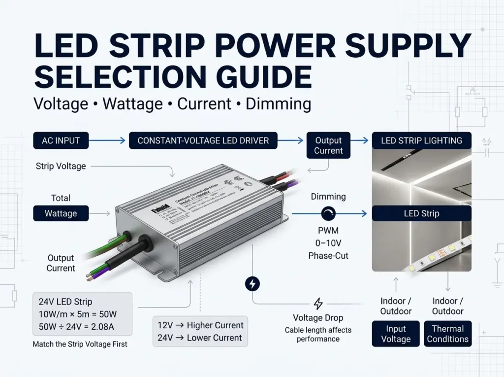
For a constant-voltage load, nominal power and current can be estimated with:
[ P = V I ]
[ I = ]
For example, consider two 5m branches of 24V LED strip rated at 12W/m:
| Load item | Calculation | Nominal result |
|---|---|---|
| Branch A power | 5m × 12W/m | 60W |
| Branch A current | 60W ÷ 24V | 2.5A |
| Branch B power | 5m × 12W/m | 60W |
| Branch B current | 60W ÷ 24V | 2.5A |
| Combined load | 60W + 60W | 120W |
The combined nominal current at 24V is 5A if both branches are supplied from the same 24V output and their loads are additive. Confirm actual branch topology and each output/channel rating before selecting a driver.
This calculation is not a driver recommendation by itself. Verify the selected model’s total output rating, per-channel current limits, allowable branch arrangement, thermal derating and installation instructions. If a multi-channel driver is used, total capacity does not override an individual channel’s rating.
Check the wiring and voltage distribution
Measure or calculate voltage drop on the 24V output wiring using the actual conductor size, length and load. Long low-voltage runs can produce different voltage at the beginning and end of an LED strip. That may cause uneven brightness or make a system appear to dim inconsistently even when the control interface is operating as intended.
Record the driver-to-load cable length, branch points, connector type and any planned field wiring changes. Keep power distribution and dimming control wiring identified separately in the project documentation.
3. Verify the 0–10V Controller and Driver Interface
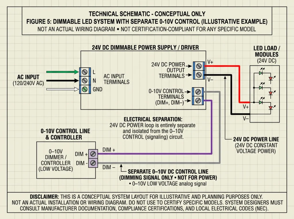
The 0–10V label identifies a control approach, but it does not settle every interface detail. Confirm the selected controller and driver are designed to work together.
Confirm the exact control interface
Check the datasheets for both devices. Confirm the stated control range, wiring requirements, polarity, control-input characteristics and any compatibility notes. Some products use related but not identical 0–10V or 1–10V behavior; do not assume the same voltage range, dimming response or off behavior without documentation.
Also establish how the interface operates electrically. Depending on the design, a controller may source or sink current, while a driver’s dimming input has its own electrical requirements. Verify that the two sides are compatible according to their manufacturers’ documentation rather than inferring compatibility from terminal labels alone.
| Interface check | What to verify | Possible issue if mismatched |
|---|---|---|
| Control range and behavior | The specified 0–10V or 1–10V operating range and response | Unexpected dimming range or off behavior |
| Polarity and terminals | Correct DIM+ / DIM− connections as documented | Control may not respond as intended |
| Electrical loading | Controller source/sink capability and driver input requirements | Control signal may not reach the expected level |
| Wiring topology | Cable type, length, routing, connections and permitted device count | Unstable or inconsistent control behavior |
| Dim-to-off | Whether the driver supports it or separate switching is required | Load may remain at a low output instead of turning off |
These are checks, not diagnoses: any symptom should be confirmed against the exact controller and driver documentation and measured conditions.
Measure the control signal at the driver
If the control signal is in doubt, measure it at the driver’s control terminals using an appropriate meter and the manufacturer’s recommended procedure. Record the control command and measured voltage at full output, mid-range and the lowest required setting.
If the controller indicates one level but the signal arriving at the driver differs, investigate the control wiring, connections, controller loading and interface specifications before concluding that the driver is at fault. Measurements on an installed system should be performed by qualified personnel using suitable instruments and safe procedures.
Review wiring topology and control-zone loading
Document the control cable type, length, routing, connection method and number of drivers on the same control zone. Follow the controller and driver instructions for control wiring separation, grounding and maximum connected devices. Avoid assuming that a wiring arrangement validated for one controller or driver model applies to another.
Decide how the system should turn off
A control signal at or near 0V does not necessarily mean every driver will disconnect its output or remove power from the LED load. Some systems dim to a very low level; others support a defined dim-to-off behavior; some applications require separate switching. Confirm the selected model’s specification and write the expected behavior into the project acceptance criteria.
For further background, see Lutron’s technical note, 0–10V Control Topology. It explains why interface details and the actual control/driver combination matter even after basic compatibility information has been collected.
4. Test the Full Dimming Range with the Actual LED Load
The most important test is not whether the light turns on at full output. It is whether the driver, controller and real LED load behave acceptably across the range required by the project.
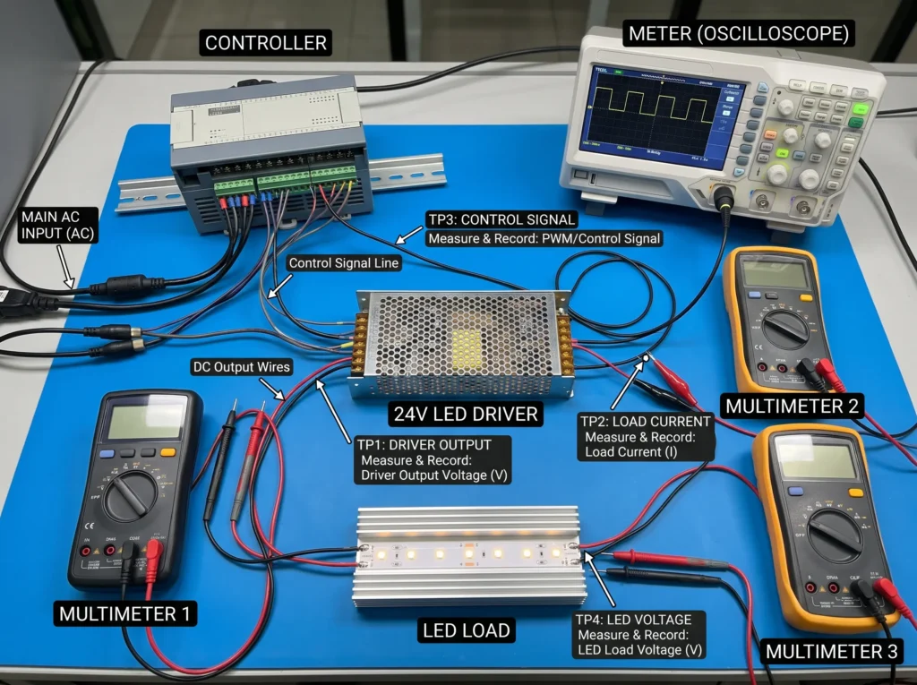
Test the required operating points
Use the project specification and the driver’s published dimming behavior to select test points. At a minimum, include full output, one or more intermediate levels, the lowest required output, and any transition or off state that matters to the application. Add more points around a problem area if the dimming response is not smooth.
At each point, record the test condition and the observed result:
| Test point | What to observe or measure | Acceptance basis |
|---|---|---|
| Full output | Start-up, steady operation, output consistency and noise | Project requirement and driver specification |
| Intermediate levels | Smoothness, visible steps and consistency across fixtures | Required dimming behavior |
| Lowest required level | Flicker, dropout, sudden jumps or unexpected shutoff | Project-defined minimum stable output |
| Transition up/down | Response when moving between levels; repeatability | Project requirement and driver data |
| Dim-to-off, if required | Whether the load turns off as specified | Driver specification and project control logic |
| Power-cycle recovery | Restart state and stability after power is restored | Defined project acceptance criteria |
Also record the controller command, measured control signal where relevant, exact load, operating conditions and any audible noise. A control percentage is not necessarily the same as a measured light-output percentage.
A control percentage is not necessarily the same as a measured light-output percentage. If the project specifies illuminance, luminous output, flicker metrics or another measurable performance requirement, use the appropriate method and instrument rather than relying only on a wall-control display or visual impression.
Check start-up, transitions and recovery
Test more than steady-state levels. Move from full output to low output and back, and check whether the system starts reliably at the required settings. Repeat transitions to identify intermittent behavior. If the project requires a particular recovery state after power is restored, test that condition and document the result.
If flicker or dropout occurs only at the low end, do not immediately assume the driver is defective. Possible causes include controller/driver incompatibility, control signal behavior, an unsuitable load, wiring issues or a driver limitation. Compare the observed result with the manufacturer’s specifications and compatibility information.
Test with the actual controller and LED module
A test using a different controller or substitute LED load may be useful for initial screening, but it does not establish project compatibility. For approval, use the specified controller and the actual LED load, or document any approved equivalent used during the test. Record model numbers and configuration details so the result can be reproduced.
5. Validate the System Under Representative Project Conditions
A single driver operating on a short test lead is not a complete representation of a commercial installation. Validate the configuration that the project will actually use.
Test minimum and maximum connected loads
Where the project has different operating configurations, test the relevant minimum and maximum loads within the manufacturer’s limits. A controller/driver combination may behave differently with one fixture than with a full zone of fixtures. Confirm the number of drivers and loads allowed on each control circuit.
Evaluate multiple drivers on one control zone
Connect the intended number of drivers using the planned control topology. Check whether fixtures start together, respond consistently and remain stable at low output. If brightness differs, determine whether the difference comes from the control signal, LED load variation, power distribution, driver settings or the products themselves.
Do not assume that multiple individually successful bench tests prove that a complete zone will behave identically.
Symptoms to investigate during validation
| Observed symptom | Possible causes to investigate | Useful next check |
|---|---|---|
| Flicker near minimum output | Controller/driver mismatch, low-end behavior, load or wiring conditions | Confirm the interface specification and repeat the low-end test |
| Some fixtures appear brighter than others | LED variation, output wiring voltage drop, differing loads or control response | Compare branch loads and measure voltage at representative points |
| Lights do not turn fully off | Driver may not support dim-to-off, or separate switching may be required | Check the exact driver behavior and project control logic |
| One zone behaves differently from another | Different wiring, device count, load arrangement or product configuration | Compare model numbers, topology and test conditions |
| Behavior changes after warm-up | Operating temperature or thermal limits may affect performance | Repeat the test under representative thermal conditions |
These symptoms do not identify a single root cause by themselves. Record observations and verify the cause before changing a product or approving a substitute.
Include realistic cable lengths and operating conditions
Use representative power and control cable lengths, conductor sizes, connection methods and routing. Check the system under the ambient conditions relevant to the installation and follow the driver’s specified thermal limits. If the final enclosure or mounting arrangement affects heat dissipation, include that arrangement in the validation.
Repeat critical tests after power cycling and, where required by the project, after the system has reached a representative operating temperature. Record any changes rather than treating one successful run as conclusive evidence.
6. Establish Pass/Fail Criteria for Project Approval
The approval decision should be based on defined requirements and recorded results—not a general statement that the lights “look fine.”
Use a test matrix such as the one below and adapt it to the project specification.
| Test item | What to record | Basis for acceptance |
|---|---|---|
| Driver and load identity | Exact model numbers, revisions and configuration | Approved bill of materials and current datasheets |
| Input and output | Actual input, 24V output and load current where required | Product ratings and project electrical requirements |
| Control interface | Controller model, wiring and measured control signal where relevant | Manufacturer interface specifications |
| Dimming range | Required settings, stability and output behavior | Project dimming requirements and driver data |
| Flicker and visual consistency | Observed or instrument-measured results | Project specification and applicable test method |
| Multi-driver operation | Number of devices, zone behavior and deviations | Approved control topology |
| Thermal and installation conditions | Ambient conditions, mounting and enclosure | Product instructions and project requirements |
| Final result | Pass, fail or further review | All mandatory criteria satisfied |
Use these result labels consistently:
| Status | Use when | Required next step |
|---|---|---|
| Pass | All mandatory project criteria are met and the evidence is complete | Save the results with the approved configuration |
| Fail | A mandatory requirement is not met | Document the deviation and correct or replace the affected component/configuration |
| Requires Further Review | Testing is incomplete, evidence is insufficient or a deviation needs a technical decision | Identify the missing evidence or decision and retest if necessary |
A result should be marked Pass only when all mandatory project criteria are met. Do not invent a universal numeric threshold for flicker, minimum dimming or temperature. Those limits must come from the project requirements, applicable standards, and the exact products being evaluated.
Keep the supporting evidence with the approval package: instrument readings where applicable, photos or videos of observed behavior, wiring configuration, datasheet revisions, deviations and corrective actions. If the controller, driver, LED module or wiring changes after approval, assess whether the affected tests need to be repeated.
7. Which FAHOLD 24V Driver Should Be Evaluated?
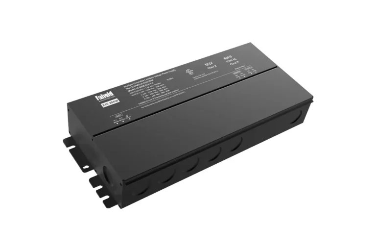
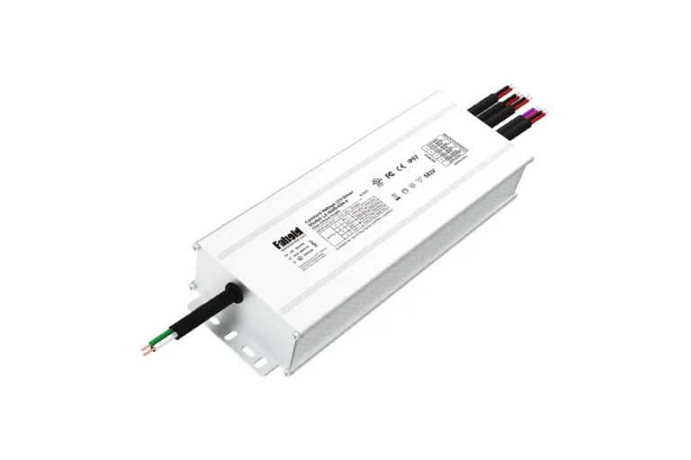
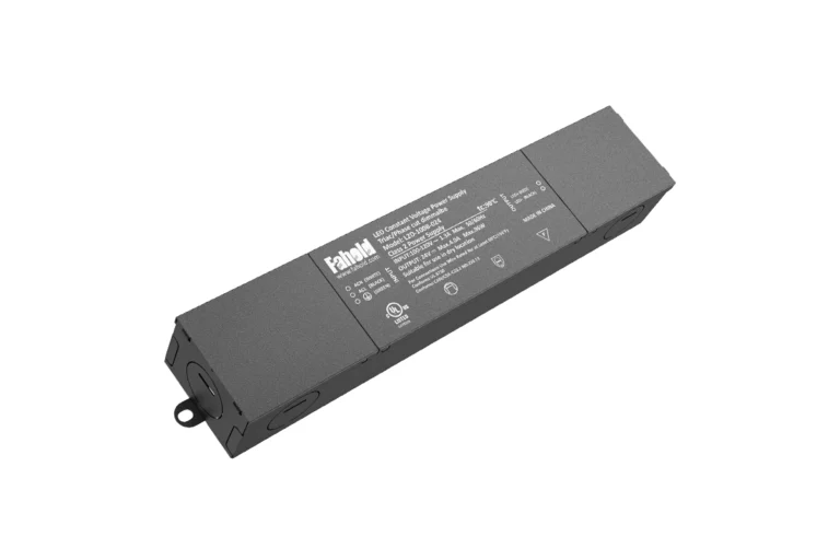
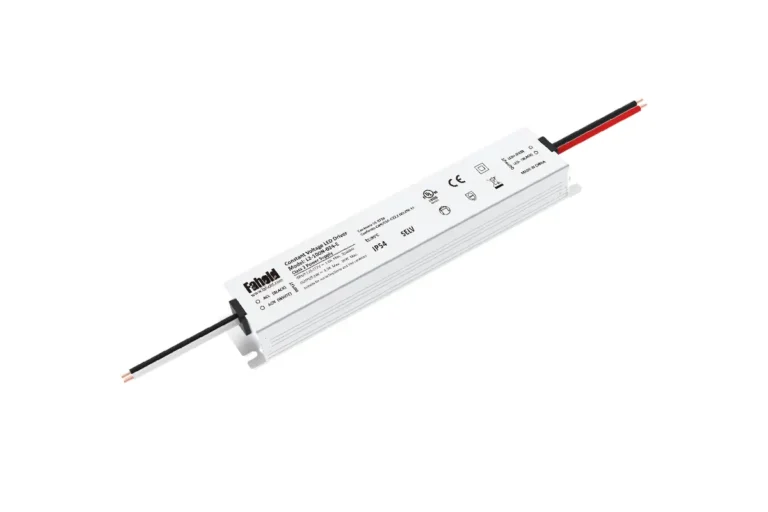
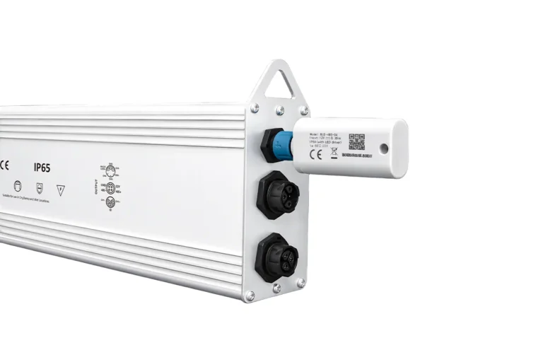
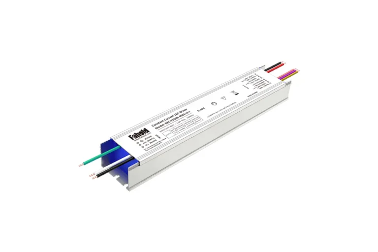
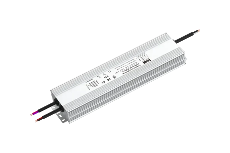
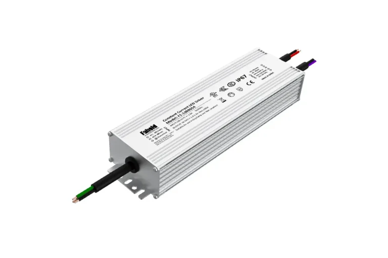
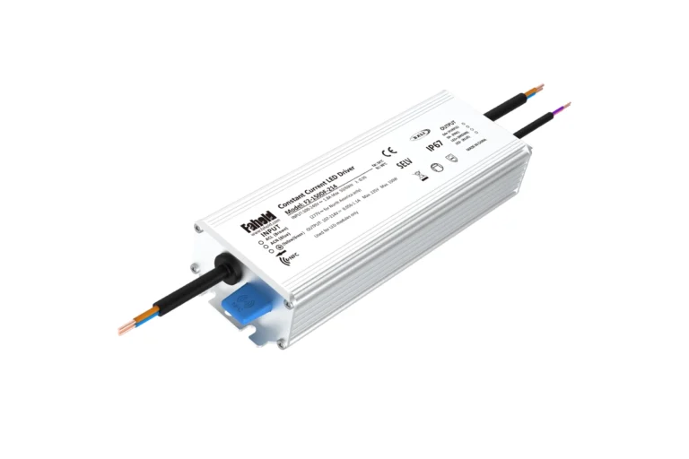
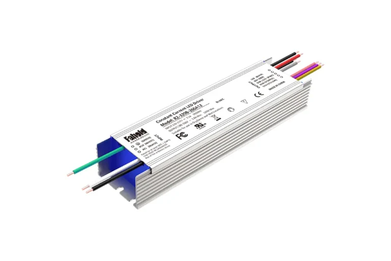
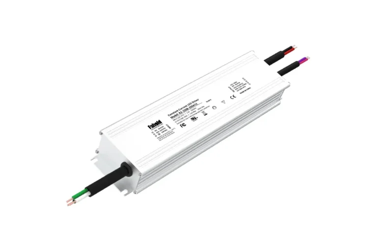
The FAHOLD L2-A Series is an enclosed 12V/24V constant-voltage power-supply platform with 100–277Vac rated input. Depending on the exact model and configuration, the series supports different dimming options, including 0–10V. The family includes single-output and multi-channel variants, so model-specific ratings matter.
Treat L2-A as a candidate for evaluation, not as a blanket compatibility claim. Before a sample test, verify the exact part number, output voltage, total wattage, per-channel limits, selected dimming configuration, enclosure, thermal requirements and certification documentation.
For a project using 24V strips with 0–10V control, use a model-specific review:
| Selection check | Evidence required before approval |
|---|---|
| Output type and voltage | Datasheet confirms 24V constant-voltage output for the exact model |
| Total and per-channel capacity | Load calculation compared with rated output and channel limits |
| Dimming configuration | Exact part number or configuration explicitly supports the required 0–10V interface |
| Controller compatibility | Driver and controller documentation reviewed; actual combination tested as required |
| Installation and certification | Enclosure, thermal conditions, installation instructions and relevant records checked |
| Sample validation | Results recorded using the intended controller and representative LED load |
FAHOLD’s existing 24V 0–10V LED Driver Selection Guide covers the earlier selection stage. Use this article for the subsequent validation stage: demonstrating that the chosen combination meets the project’s acceptance criteria.
8. What to Include in the Project Approval Package
A concise approval package helps the project engineer, contractor, purchasing team and supplier work from the same configuration.
| Document or record | Minimum information to include |
|---|---|
| Product identification | Driver, controller and LED load manufacturer/model numbers; revisions and configuration |
| Technical documentation | Current datasheets and applicable certification records |
| Electrical design | Input/output ratings, load calculation, branch layout and cable details |
| Control design | Control wiring topology, number of drivers per zone and dimming configuration |
| Test evidence | Test points, results, instruments and operating conditions |
| Deviations and retests | Observed issues, corrective actions and retest results |
| Approval decision | Approved, rejected or pending further review, with reviewer/date if required by the project |
The package should make the result reproducible. If another team member cannot identify the tested products and wiring arrangement from the record, the evidence is not complete enough for a reliable handoff.
Frequently Asked Questions
Does a 24V 0–10V LED driver work with every 0–10V controller?
No. Verify the exact control interface, electrical characteristics, wiring requirements and manufacturer compatibility information. A shared “0–10V” label does not guarantee the required dimming performance.
Why does a 24V LED strip flicker at low dimming levels?
Possible causes include an incompatible control/driver combination, control-signal behavior, load or wiring conditions, or the driver’s minimum dimming performance. Test the actual system and compare results with the product specifications before assigning a cause.
Does 0V on the dimming input always turn the driver off?
No. The behavior depends on the driver design and its specification. Confirm whether the project requires dim-to-off or separate switching and test that behavior with the selected controller.
Should multiple drivers be tested on the same controller?
Yes, when the final project uses multiple drivers on one control zone. Verify the controller’s permitted loading and the driver instructions, then test the intended number of devices and the planned wiring topology.
What should be included before approving a 24V 0–10V LED driver?
At minimum, document the exact driver, controller and LED load; electrical ratings; control wiring; dimming results; operating conditions; relevant certification records; and the pass/fail decision against predefined criteria.
Need Help With Your LED Power Supply Project?
Tell us what you are working on. We will review your application and recommend the most relevant FAHOLD solution.