Table of Contents
A replacement 12V LED driver may turn the lights on at full brightness yet flicker, buzz, refuse to dim, or shut off unexpectedly when the existing dimmer is used. Matching 12V output and wattage is necessary, but it does not establish dimming compatibility. The replacement must also match the LED load type, control method, usable output current, wiring arrangement, and installation conditions.
Before requesting a quote, document the old driver’s label and the actual dimmer or controller model. If that information is missing, an apparently equivalent 12V dimming LED driver is still a guess. This guide provides a replacement decision process, two load examples, and a field-acceptance checklist for commercial LED strips, retail displays, cabinet lighting, and architectural fixtures.
First, Confirm the Driver Is Actually the Problem
Replacing a driver is reasonable when it is defective, unavailable, no longer compatible with an updated control system, or unsuitable for the current installation. But dimming problems can originate elsewhere. A flickering strip may have a poor connection, an overloaded controller, significant voltage drop, a defective LED section, or incompatible dimmer settings while the power supply itself is still operating normally.
| Observed problem | Possible causes other than the driver | What to document before replacing it |
|---|---|---|
| Lights fail to turn on | No upstream power, switch/control failure, open circuit, reversed DC polarity, failed LED load | Input/control status, load condition, protection state |
| Lights work at full output but do not dim | Wrong dimmer mode, control wiring issue, unsupported interface, incorrect controller configuration | Exact dimmer/controller model and control topology |
| Flicker or flashing only at low output | Low-end incompatibility, minimum-load condition, unstable control waveform, LED-load interaction | Dimming level, affected circuits, controller settings |
| One strip section is much dimmer | Excessive cable or strip voltage drop, a loose connection, uneven branch loading | Branch lengths, conductor sizes, load distribution |
| Intermittent shutdown at higher brightness | Overload, thermal protection, wiring fault, unsuitable environmental conditions | Full-load current, ambient temperature, installation details |
Do not diagnose an energized mains circuit from appearance alone. A qualified electrician or technician should isolate power and follow the applicable electrical code and manufacturer’s service instructions before inspecting or changing wiring. If the original driver failed through water damage, overheating, or a damaged connector, correct the underlying installation issue before installing another unit.
Read the Existing Driver Label Before Choosing a Replacement
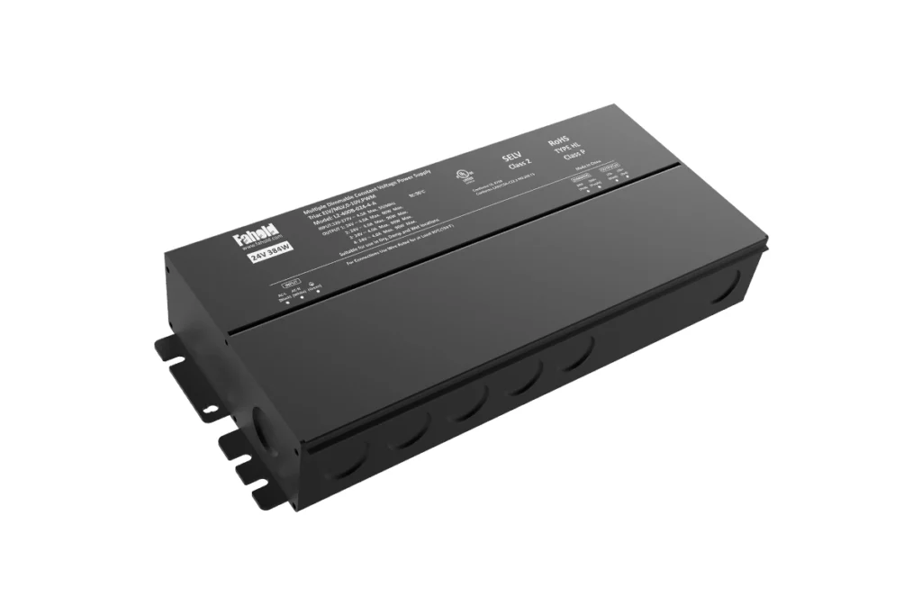
Start with photographs of the old driver’s entire nameplate, terminal labels, and how it was installed. Record the manufacturer and complete model or configuration suffix. When the original datasheet is available, use it rather than interpreting marketing descriptions.
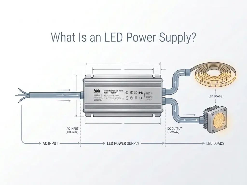
Do Not Confuse AC Input with 12V DC Output
A driver marked 100–120Vac input / 12Vdc output is not the same as a 12V input device. The first value specifies the building supply; the second specifies the LED load voltage. Some North American commercial buildings have nominal 277Vac circuits. A 100–120Vac driver cannot be installed on a 277Vac supply simply because both drivers produce 12V DC.
Check the actual input-voltage range and mains-dimming arrangement. A supply that accepts 100–277Vac in normal operation is not automatically qualified for every 277V phase-cut dimmer; the controller/driver combination must be supported by the manufacturer.
Confirm Constant Voltage or Constant Current
Most conventional 12V LED strips with integrated current-limiting components are constant-voltage loads. Other lighting modules are designed for constant-current drivers and may carry a voltage range rather than a regulated 12V output requirement. These two driver types should not be interchanged. If the original label states an output current such as 350mA or 700mA with a voltage range, confirm the LED module’s requirements before treating it as a 12V constant-voltage replacement project.
Preserve the Details That Affect Compatibility
| Existing-driver information | Why it is needed | Replacement check |
|---|---|---|
| Full model and variant code | Suffixes may separate dimmable and non-dimmable versions | Obtain the exact replacement datasheet |
| AC input and operating frequency | Must match the site’s actual electrical supply | Verify the candidate’s rated input |
| Output type and DC voltage | Must match the LED load architecture | Confirm 12V regulated constant-voltage output where required |
| Rated output wattage and current | Determines full-load capacity | Check usable continuous rating and any derating |
| Number of output channels | Each branch may have an individual current limit | Verify channel count and rating separately |
| Dimming interface and terminal diagram | Determines control compatibility | Match existing dimmer/controller and wiring architecture |
| Enclosure, location rating, and dimensions | Determines physical and environmental suitability | Confirm mounting, cable entry, clearances, IP, and approvals |
| Safety listing and installation conditions | Project requirements can be model-specific | Request applicable documentation for the actual SKU |
Identify Which Device Controls the Brightness
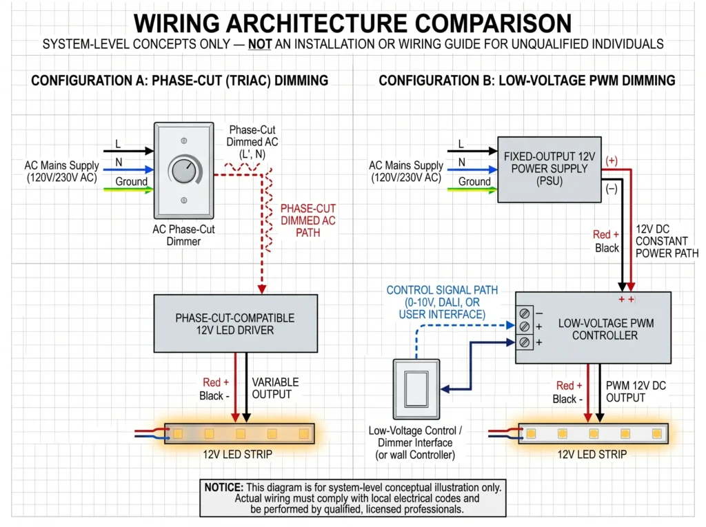
The most consequential replacement mistake is assuming that all products described as “12V dimmable” accept the same dimmer. They do not. Determine whether dimming takes place on the AC input, through a separate low-voltage control signal, or after the power supply.
Phase-Cut Wall Dimming: TRIAC, ELV, and MLV
In a phase-cut installation, a compatible wall dimmer modifies the AC waveform supplied to a driver designed to interpret that signal. Forward-phase, reverse-phase, and magnetic-low-voltage arrangements can have different load and compatibility requirements. A driver that supports one method cannot be presumed compatible with every dimmer sold under another label.
For a replacement, obtain the wall dimmer’s exact make/model and, when possible, the old driver’s compatibility list. Check the AC supply and minimum operating load. A dimmer/driver mismatch can cause flashing, dropout, limited dimming range, or audible noise. Lutron’s voltage-driver application guidance illustrates why low-end trim and system-level testing matter; its product-specific settings should not be copied to an unrelated driver.
Separate 0–10V Control: Check the Signal, Not Only the Two Wires
In a 0–10V installation, the driver receives a control signal separate from the LED’s 12V power output. Confirm the controller’s electrical design, control polarity, wiring/reference requirements, dimming range, and how a zero or minimum command is interpreted. Do not assume that “0V” automatically turns every driver completely off. Existing building controls and the replacement driver’s terminal documentation must agree.
PWM Input Versus External PWM Controller
The phrase “PWM dimming” can describe different arrangements. A driver may accept a PWM command at dedicated control terminals, or a fixed-output 12V supply may power a separate PWM module that switches the LED strip on the DC side. A PWM-compatible control input does not prove that the driver delivers PWM-switched power at its output. For an external controller, its voltage rating and per-channel current capacity remain separate requirements.
See FAHOLD PWM LED driver selection page if the project’s control interface is specifically PWM; it is a different selection question from the general 12V replacement process.
| Existing control arrangement | What the replacement must support | Wrong assumption to avoid |
|---|---|---|
| Wall phase-cut dimmer ahead of driver | Compatible TRIAC / ELV / MLV method, AC input, and dimmer/load behavior | Any “dimmable” 12V supply works with the wall dimmer |
| Separate analog 0–10V control | Correct control-input type, wiring, range, and off behavior | A 12V output means the driver accepts 0–10V control |
| PWM signal at dimming input | Compatible signal level, polarity, frequency, and input topology | PWM input means PWM-switched output |
| Fixed 12V supply followed by PWM controller | Supply permitted for the load; controller rated for voltage/current/channels | The power supply itself must be connected to the dimmer’s PWM signal |
Size the Replacement by Real Load and Output-Channel Limits
The replacement must supply the LED system at its maximum intended operating condition. Adding wattage to compensate for a dimming problem may not help if the problem is the control interface or wiring. Conversely, choosing a unit from its advertised wattage class without examining output current can overload a branch.
Worked Example: A 12V Retail Display Strip
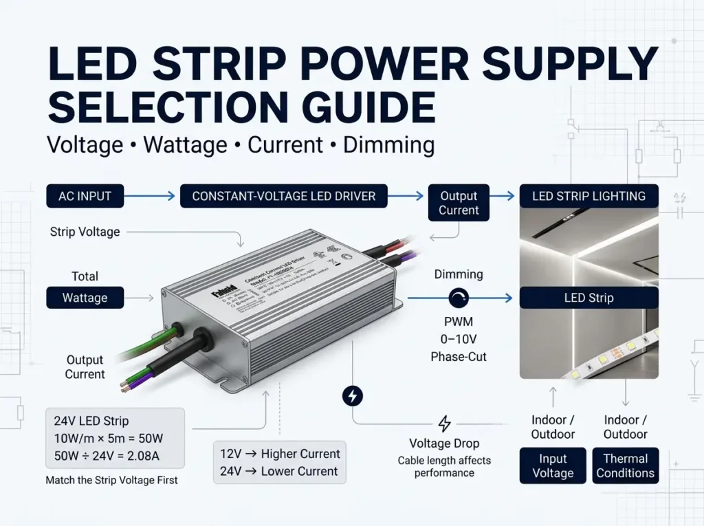
Suppose a retail cabinet uses four meters of constant-voltage LED strip rated at 10W/m. The connected load is 4 × 10 = 40W; the calculated nominal output current is 40W ÷ 12V = 3.33A. A replacement must provide at least the usable continuous output required by the load after applying the manufacturer’s loading and thermal derating rules, with any additional project margin justified by the design.
The existing dimmer could still make a driver with ample output capacity unsuitable. Before approving a 12V/60W-class candidate, check that its actual current rating, control input, minimum-load conditions, and installation temperature match the system. The calculation is illustrative, not a recommendation for a particular SKU.
Worked Example: Three Branches on a Shared Driver
Consider three separate 12V display branches rated at 25W each. The combined connected load is 75W, and the combined nominal current is 6.25A. Each branch draws about 2.08A. If a proposed multi-output driver has two outputs rated at 5A each, the branch allocation must keep each output at or below its individual limit and the total within the applicable driver rating. Two branches on one 5A output represent about 4.17A in this example; the third branch may use the other output if the manufacturer’s wiring and load-sharing instructions permit that arrangement.
Multiple outputs do not automatically represent separately addressable dimming zones. The dimming control may be shared across all outputs. Confirm this before a fixture manufacturer promises independent shelf or display control.
For broader calculations covering LED-strip length, current and voltage drop, see FAHOLD LED strip power supply engineering guide. This replacement article focuses on the compatibility decisions that must follow those calculations.
Check Physical Installation, Protection, and Compliance
A replacement can be electrically suitable yet fail the installation review. Measure the available mounting space, cable entry locations, required junction-box arrangement, ventilation, and access for maintenance. Document whether the driver is in a protected interior space, a damp enclosure, or an exposed area requiring a verified environmental rating.
An outdoor LED strip does not automatically require an IP67 power supply if the driver itself is installed in an appropriate protected location. The opposite is also true: an indoor-rated enclosure should not be moved into an exposed location merely because the output is still 12V. Check the manufacturer’s actual installation instructions and required approvals. IP protection, North American electrical listings, and any Class 2 designation are distinct, model-specific considerations; none should be inferred from the nominal 12V voltage alone.
If the original driver repeatedly overheated or shut down, investigate ambient temperature, mounting orientation, enclosure temperature, available ventilation, and continuous output load. A higher-wattage replacement is not a substitute for a suitable thermal design.
Test Dimming Compatibility Before Approving a Replacement
For an OEM or commercial project, the sample evaluation should use the actual dimmer/controller model and a representative LED load. A bench test with a different controller may show that the power supply works, but not that it will work with the installed system.
Use the following as a project test record. Pass criteria should be defined from the control specification, lighting design, and manufacturer documentation rather than invented as universal numbers.
| Test condition | What to observe and record | Acceptance basis |
|---|---|---|
| Power-on at normal control setting | Consistent startup, no repeated flashing or protection cycling | Project startup requirement and driver specifications |
| Full output under maximum intended load | Stable operation and no overload/shutdown | Rated output, load and temperature limits |
| Midrange dimming | Smooth response and consistent output across fixtures | Controller behavior and project visual requirements |
| Lowest required light level | No dropout, stepping, unstable startup or unwanted glow | Specified low-end performance and low-end trim capability |
| Off / dim-to-off behavior | Complete off or specified standby behavior | Actual control/driver design; never assume zero signal equals off |
| Repeated on/off and dim-up/down | Reliable return from off and stable ramping | Control-system operating sequence |
| Multiple drivers on one control | Consistent response without unwanted mismatch | Control capacity and matching requirements |
| Extended operation in intended enclosure | Thermal stability and acceptable acoustic behavior | Product instructions and installation temperature limits |
| Camera-sensitive or moving-display scene, if relevant | Assess temporal light artifacts using appropriate test method | Project-specific flicker/stroboscopic criteria |
The U.S. Department of Energy notes that LED temporal light artifacts are affected by driver behavior and its interaction with dimmers. Its flicker fundamentals explain why a simple “flicker-free” claim cannot replace testing of the actual system. For repeat orders, preserve the approved dimmer model, driver SKU, LED strip SKU, control settings, and test record so later batches can be checked against the same baseline.
When a Replacement Still Flickers or Will Not Dim
If the proposed driver meets the basic electrical ratings but the lights do not behave correctly, isolate the failure systematically rather than trying several random power supplies. Qualified technicians should take any necessary electrical measurements using safe, appropriate equipment.
| Symptom after replacement | First investigation | What may resolve it |
|---|---|---|
| Full brightness only | Control method does not match, wrong terminals, absent control signal | Verify controller type, wiring diagram and exact driver configuration |
| Flicker near minimum | Unsupported low-end range, incompatible dimmer/driver behavior, poor connections | Check tested compatibility and manufacturer-authorized low-end trim |
| Light stays on at minimum command | Driver’s minimum output or off behavior differs from expectation | Confirm dim-to-off requirement and whether separate AC switching is needed |
| Flicker only when other loads switch | Supply disturbance, shared circuit/control issue, wiring noise | Review circuit/control arrangement and installation conditions |
| Buzzing from dimmer or driver | Phase-cut interaction or other component behavior | Confirm supported dimmer model, load and operating mode |
| Brightness differs between branches | Branch loading, voltage drop, unequal cabling, control mismatch | Verify each branch, conductor/run and output rating |
| Shutdown after warm-up | Excessive temperature, insufficient usable capacity, installation problem | Review thermal derating, ventilation and maximum load |
For phase-cut systems, low-end trim may improve an otherwise compatible combination, but trim adjustments should follow the relevant dimmer and driver instructions. Do not use trim as a workaround for an electrically incompatible product. If the controller itself is obsolete or unsupported, the reliable solution may require changes to the control system rather than a replacement driver alone.
FAHOLD 12V Dimmable Driver Platforms to Evaluate
FAHOLD 12V dimmable constant-voltage range provides several starting points for replacement and OEM evaluation. Platform descriptions are a routing guide, not a promise that every model accepts every dimmer.
| Existing project condition | Starting FAHOLD platform | What must still be verified |
|---|---|---|
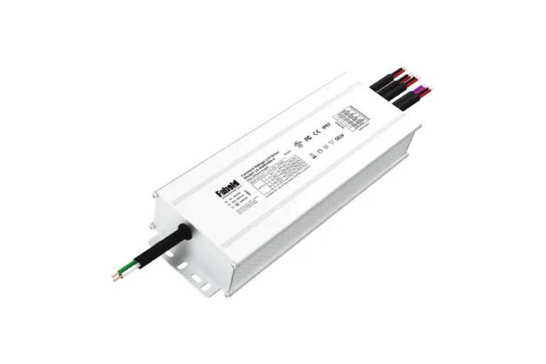
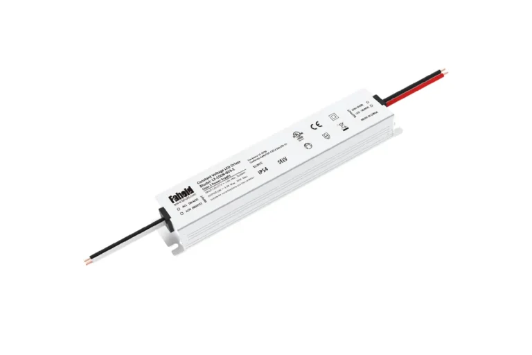
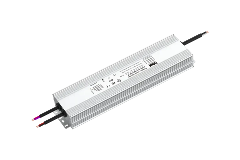
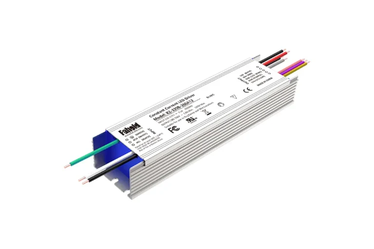
| 12V commercial LED strips needing an enclosed supply and protected field connections | L2-A enclosed platform | Dimmable Type B/configuration, exact control input, output/current, junction-box and certification requirements |
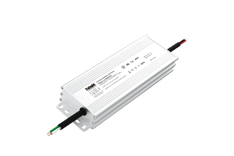
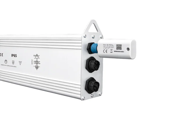
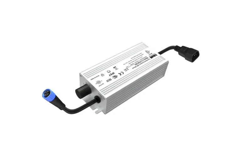
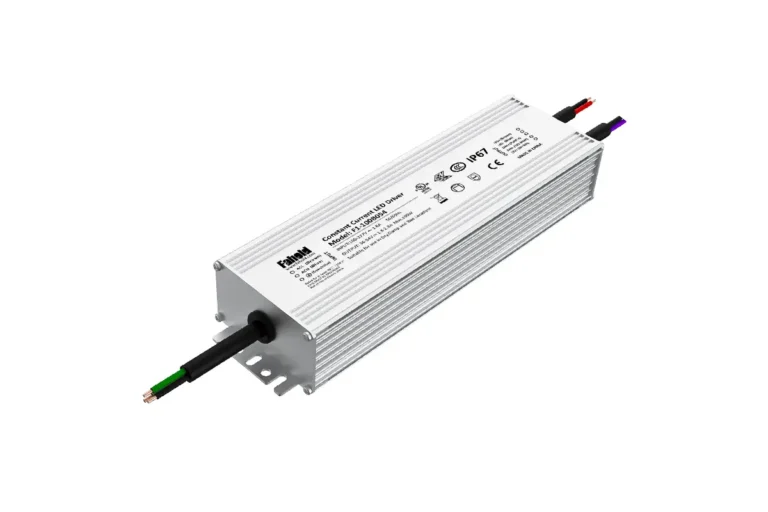
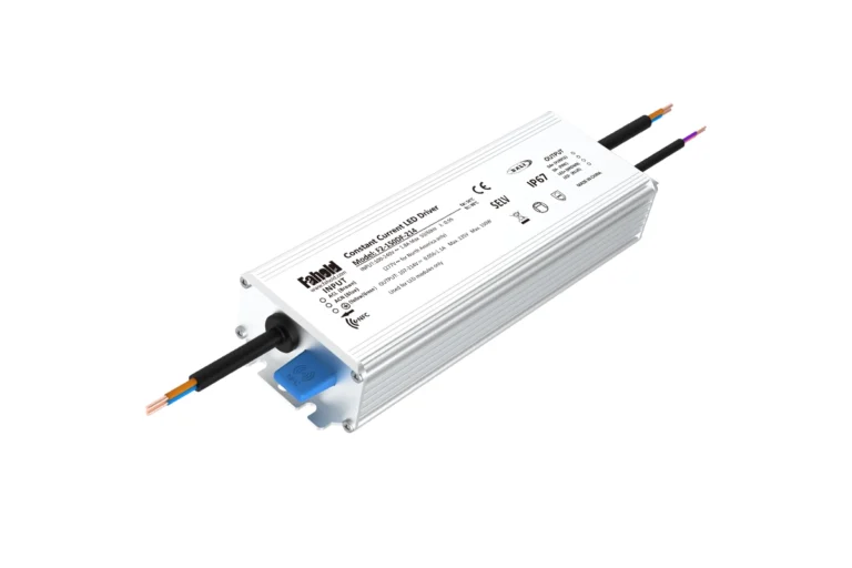
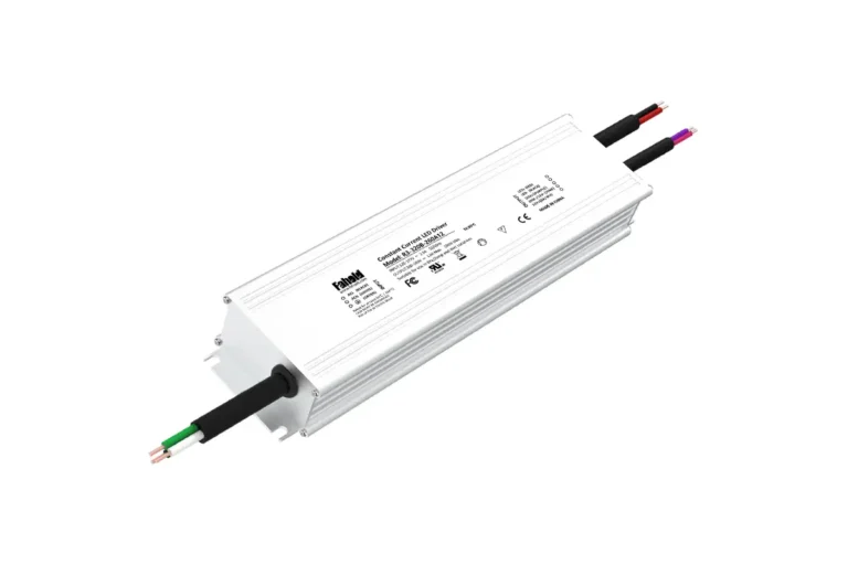
| 12V architectural or landscape system where the driver location requires higher ingress protection | L2-F IP67 platform | Actual waterproof model, corrected datasheet, output-channel ratings, dimmer/control compatibility and installation details |
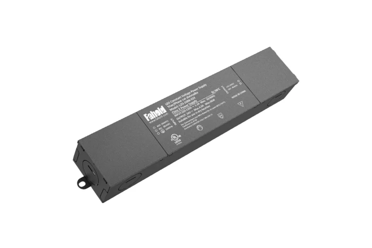
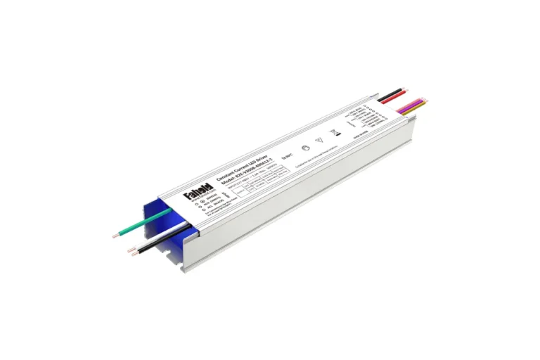
| 12V system using compatible 100–120Vac TRIAC / ELV / MLV phase-cut wall control | L2D Type B | Actual wall dimmer, 100–120Vac input, 12V load, 60W model limits and mounting conditions |
The L2-A series covers enclosed constant-voltage configurations, while the L2-F series is the waterproof platform. For L2D, Type N is non-dimmable and must not be specified as a substitute for a Type B dimming configuration. The L2D platform is rated for 100–120Vac input; it must not be substituted into nominal 208V, 240V, or 277V circuits.
For an available-product overview rather than another technical tutorial, compare FAHOLD 12V dimmable LED drivers and power supplies by wattage, control requirements, output channels, enclosure and installation needs. Final model approval should follow a datasheet and controller review.
What to Send Before Requesting an Equivalent Driver
A short, complete replacement specification is more useful than an inquiry asking only for a “12V dimming LED driver.” Share the information below with your engineering or purchasing contact.
| RFQ field | Information to provide |
|---|---|
| Original product | Manufacturer, full model/variant, nameplate and datasheet photo |
| Target market and AC input | U.S./Canada or other; actual supply voltage and frequency |
| LED load | Strip/module/fixture model, constant-voltage requirement, 12V rating |
| Maximum load | Total watts, current and length or number of fixtures |
| Output distribution | Number of branches, current per branch, existing channel arrangement |
| Dimming controls | Dimmer/controller manufacturer and model; TRIAC/ELV/MLV, 0–10V, PWM or other verified method |
| Performance needs | Minimum light level, off behavior, flicker/camera sensitivity, acoustic requirements |
| Installation | Indoor/protected/damp/exposed location, dimensions, junction-box and cable-entry requirements |
| Compliance | Required certifications, Class 2/listing and project documentation |
| Procurement | Quantity, schedule, sample-testing requirements and destination |
An existing wiring diagram and representative LED strip sample can resolve questions that a catalog description cannot. Ask for a candidate datasheet, control-interface information, and any available dimmer compatibility evidence before purchasing a batch. Use a sample approval step where the existing control ecosystem is critical to the project.
Frequently Asked Replacement Questions
Can I Replace a 12V 40W Dimmable Driver with a 12V 60W Model?
Potentially, if the 60W unit has the correct regulated 12V output, supports the existing dimming method and load conditions, and meets the installation requirements. Higher rated capacity does not by itself guarantee compatible dimming, low-end performance, or freedom from flicker. Check minimum load and derating information as applicable.
Is a 12V Non-Dimmable LED Power Supply an Equivalent Replacement?
Not when the existing system expects a dimming function from the driver. A compatible fixed-output supply may be usable in a different architecture with a downstream low-voltage PWM controller, but that is not a drop-in replacement for a driver receiving 0–10V or phase-cut commands.
Can Any 12V Dimmable Driver Work with a TRIAC Wall Dimmer?
No. Confirm whether the driver supports the actual phase-cut method and AC input, and verify the specific wall dimmer and connected load. “Dimmable” alone does not identify the supported control interface.
Why Does the LED Strip Flicker Only at Low Brightness After Replacement?
Possible causes include dimmer/driver mismatch, minimum-load conditions, unsupported low-end settings, control instability, or wiring faults. Compare the controller and driver specifications, verify the load, and test the approved combination throughout the required dimming range. Do not assume the driver is faulty solely because the symptom appears at low output.
Can One Multi-Channel Driver Replace Several Single-Output Drivers?
Only after checking every output’s current limit, total usable capacity, control grouping, wiring/branch requirements, protection arrangement, and approvals. Multiple DC outputs do not necessarily provide independent dimming zones, and the physical distribution may need redesign by a qualified professional.
Does a 12V Output Mean the Replacement Is a Class 2 Power Supply?
No. Class 2 requirements concern the actual power source and its listed electrical limitations and construction. A nominal 12V rating alone does not establish Class 2 status. Verify the applicable model-level safety documentation and intended installation.
Preserve the System Requirements When Replacing the Driver
The most reliable replacement matches the existing LED load, control interface, power distribution, and installation environment. A driver that produces 12V at full brightness but fails the required dimming behavior is not equivalent for the project. Documenting the old configuration and testing a realistic sample are worthwhile before committing to an OEM or multi-site order.
If you have the original label, controller model and connected-load details, review FAHOLD 12V dimmable LED driver options and request a model-matching review. FAHOLD can help identify appropriate L2-A, L2-F or compatible L2D Type B starting points, then confirm the selected SKU against the project’s electrical, dimming and documentation requirements before quotation or sample approval.
Need Help With Your LED Power Supply Project?
Tell us what you are working on. We will review your application and recommend the most relevant FAHOLD solution.